As the urgency to combat climate change grows, the role of Carbon Capture, Utilisation, and Storage (CCUS) in mitigating greenhouse gas emissions becomes increasingly pivotal for a more sustainable oil/gas industry. However, the entrapment of CO2 in depleted reservoirs faces a significant challenge—caprock integrity failure leading to CO2 leakages into surrounding aquifers. Previous studies have predominantly focused on CO2 storage modelling, neglecting optimisation strategies to reduce leakage risks and how such optimisation may impact storage performance. Consequently, limited knowledge exists on controlling injection constraints to optimise storage in the presence of these risks. This study centres on coupling flow-geomechanic simulation with proxy modelling to optimise CO2 storage and minimise leakage. A comprehensive workflow was devised by integrating flow-geomechanic simulation into the sensitivity analysis, employing CMG GEM and CMOST packages. The Barton-Bandis model was utilised to simulate caprock integrity failure during injection. Unlike a modelling approach that is inadequate for injection optimisation under leakage risk, the coupled geomodelling and optimisation approach not only enables CO2 leakage modelling but also serves as a powerful tool for optimising storage efficiency while mitigating the risks of caprock integrity failure and CO2 leakage.
Keywords: CO2 sequestration, Greenhouse gas, Trapping, Caprock
Carbon Capture, Utilisation, and Storage (CCUS) plays a critical role in reducing greenhouse gas emissions and paving the way for a more sustainable oil business as the pressure to address climate change increases. One major obstacle to CO2 trapping, nevertheless, is CO2 leakage and if the risk of the leakage is great, a site may not be furthered considered for storage irrespective of the site’s capacity.1 Because of its enormous abundance in the atmosphere, CO2 is a primary greenhouse gas that contributes significantly to global climate change, necessitating storage.2 Coal seams, saline aquifers, and depleted oil and gas reservoirs are a few examples of the reservoir types where CO2 sequestration may happen. Out of all the geological formations that are being examined for CO2 storage, deep saline aquifers have the highest storage potential.3 CO2 is frequently injected as a super-critical fluid into the pore spaces present in the rock formations of these reservoirs in order to minimize the quantity of pore space required. According to Kim4 an impermeable caprock that acts as a physical barrier to prevent leakage and movement of the buoyant CO2 is necessary for the geological storage of CO2.
Thick, uniform stratigraphic strata with very little permeability make up the ideal caprocks. Reviews of prospective caprocks that have been studied for CO2 storage, however, highlight the possibility that caprocks may show notable variability in their lithologic, structural, and fluid transport properties. This variability could have an impact on the CO2 storage unit's overall performance.5 Moreover, fluid leakage channels over caprocks may be provided by faults and pre-existing fracture systems.4 Furthermore, after a high-rate CO2 injection, the reservoir pressure rises, which frequently causes induced stresses greater than the sum of the least primary effective stress and tensile strength. These stresses might reactivate preexisting fractures or cause new ones to form.4 These frequently result in CO2 leaks. It has been discovered that the primary risk taken into account for the CO2 sequestration process is the free CO2 gas leaking to the surface through fissures that are either naturally occurring or artificially created. As the caprock's fissures and faults break up, injected CO2 seeps out and spreads throughout. In order to assess the stability of CO2 storage, it is crucial to keep an eye on the geomechanical changes of the storage formation.
Extensive estimate of formation features should be carried out to guarantee the viability of a proposed storage location. Numerical simulation is important in these kinds of investigations, according to Hurter6 As a result, a number of numerical simulation studies using coupled geomechanical studies have been carried out to evaluate the stability of CO2 injection. Using a coupled reservoir-geochemical reservoir simulation, Rutqvist7 assessed the effect of shear and tensile stress failure on fracture reactivation and proposed that long-term observation would be required to observe the geomechanical changes brought about by the injected fluid pressure. Using a two-dimensional simulation model, Park8 expanded on the research by assessing the impact of heterogeneity in geomechanical properties during CO2 storage as well as the influence of geomechanical characteristics on fracture reactivation.
Notwithstanding these developments, further research is still needed to determine the ideal candidate locations for CO2 storage that will prevent leaking into the environment. A more environmentally friendly future depends on our ability to comprehend how geological formation characteristics and operating factors affect long-term CO2 storage. To guarantee a safe and effective storage, it is crucial to accurately monitor the induced stresses, permeability fluctuation, poison ratio, caprock cohesiveness, and variations in the elastic modulus of the caprock. To the best of our knowledge, no research has evaluated how these regulating factors affect CO2 storage while modeling caprock integrity failure using the Barton-Bandis model.
This study assessed the viability of CO2 storage in deep saline aquifers under a range of operational circumstances using numerical modelling. Utilising artificial intelligence (AI) and proxy modelling approaches, a thorough sensitivity analysis was carried out to examine the controlling impacts of reservoir characteristics and rock parameters in a coupled geomechanical reservoir flow system. The sensitivity analysis was performed using numerical simulations as input. By using this process, the model parameters were prioritized according to how much they contributed to caprock integrity, and the most sensitive parameters and potential interactions were found. This work contributes to the knowledge of CO2 leakage that has been reported due to caprock collapse. The broad ideas and connections created in this study can be utilised to keep an eye on CCUS operations in the future.
Reservoir model
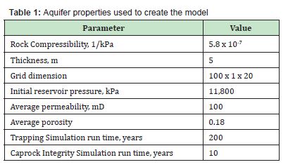
In order to evaluate the performance of CO2 sequestration and investigate the sensitivity of different parameters, a numerical simulation model (CMG-GEM) was used to create a 3D Cartesian aquifer model. The model parameters are shown in Table 1. The model was created with 3,333 grid blocks. A base case simulation incorporating structural trapping was run. Followed by a residual trapping case, and then a solubility trapping case. These were run to ascertain the amount of CO2 trapped by all these three mechanisms. The final analysis involved modelling of the barton-bandis fracture model to investigate the impact of stress on the caprock. The model included one injection well located at the middle of the aquifer for the caprock studies and at the left end for the CO2 trapping studies. CO2 injection was conducted at a constant bottom-hole flowing pressure.
CMG-Winprop was used to obtain the aquifer fluid properties. Peng-Robinson Equation of State was used to estimate the supercritical CO2 (scCO2) properties. Henry’s law was also used to model the CO2 solubility in brine. Injection of supercritical CO2 was carried out for one year. Then, the injector well was shut-in and simulation continued for 200 years to monitor the sequestration process of CO2.
Base case simulation
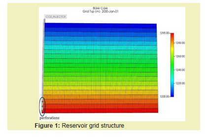
In the base case, CO2 was injected into the reservoir model at controlled bottom-hole flowing pressure of 44,500 kPa. However, the CO2 injection rate for one year was kept constant at 10,000 m3/day afterwards it was shut in for the rest of the 200 year simulation runtime. The average horizontal and vertical permeabilities were set at 100 mD. The reference pressure and water depth were equal to 11800 kPa and 1150 m, respectively. Figure 1 shows the grid structure for the simulation studies indicating the grid tops with the perforations at the last three layers in the grid.
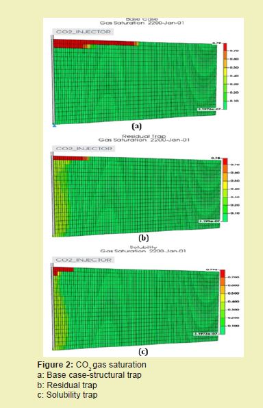
To confirm the necessity of trapping in the reservoir model, the base case simulation was run without any caprock, but only structural trap was instituted. Then another case of residual trapping and solubility trapping mechanisms were simulated. From Figure 2a, it can be seen that the injected gas moves in the reservoir and the forms a free gas cap at the end of the 200 year simulation. This is due to the fact that there is no trapping mechanism modelled in this case. Hence the need to have an impermeable structure serving as a caprock when deciding on the best site for CCUS. Even with the residual trapping and solubility trapping presented in Figures 2b and 2c, there were some volumes of CO2 making it to the surface after injecting for 1 year. This goes to show that without a caprock CO2 would find its way to the surface once injected irrespective of the inherent trapping mechanisms.
Despite the individual trapping mechanisms not being able to completely stop the migration of CO2, they did contribute to the trapping. Figure 3 and Table 2 show the different CO2 volumes trapped at the end of the 200 year simulation run time.
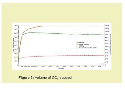

From Figure 3 it can be seen that the best trapping mechanism was the residual trapping due to hysteresis followed by the solubility trapping. The residual trapping performed better because it relies on the effect of shifting from drainage to imbibition relative permeability curves to trap the non-wetting phase, which is the CO2 gas in this case. The solubility trapping mechanism however, relies on the compositional changes of CO2 into aqueous phase at a specific pressure and temperature to trap it. Hence, the CO2 would have to be in the super-critical state to affect the trapping. This would take a long time and would be heavily dependent on pressure, temperature, and contact with fresh aqueous phase. These limiting conditions could have led to the reduced amount of CO2 trapped by the solubility trapping mechanism as compared to the residual trap.
Caprock failure studies
The injection of supercritical CO2 in the saline aquifer reservoir model can often lead to caprock failure. In this section, an analysis of this has been performed. Figure 4 shows the CO2 trapped against injected after modelling the caprock. To analyse the injection, CO2 was injected for the first five years of the run time and the injector shut-in for the next five years. Figure 5 shows the slump in cumulative injection after the 5-year injection period (1800 days). After shutting in the well it can be seen that the amount of CO2 trapped suddenly began to increase until the end of the simulation period of 10 years. For this scenario, a cumulative CO2 injection of 15,518.3 million moles in five years, and a 4,751.5 million moles of CO2 trapped after five more years of well shut-in. This represented a 30.6% of the injected CO2 trapped in the 10-year simulation. This can be seen in Figure 4 where the entrapment started after shutting in the injector well in the fifth year.

Figure 5 shows the leakage observed as a result of the caprock failure. A dual-permeability grid system was built with a fracture permeability as small as 1 x 10⁻⁸ mD in order to effectively model a zero-flow boundary along the fractures. The Barton-Bandis model was incorporated to use the tensile failure generated due to injection to increase the fracture permeability and allow leakage.

From Figure 6 it can be observed that the effective stress along the fracture decreases above the injector due to the increase in pore pressure from injection. When the normal stress drops below a set value (2000 kPa) in the fracture, the fractures open and the permeability of the fractures start to increase as seen by the red indications in Figure 6b. The continued injection leads to increased pore pressure causing more fracture opening. Thus, after the first indication of fracture opening in the second year of injection (Red Dot in Figure 6a, continuous injection for three more years led to the increment in the fracture permeability as depicted in Figure 6b.
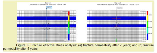
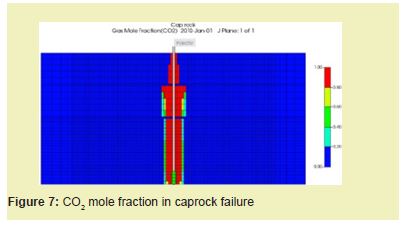
The increment in fracture permeability is a main issue with caprock integrity. The induced fractures or reopening of fractures allows the injected CO2 gas to pass into the overburden layer. After a few years of injection, the gas therefore leads to the cracking of the top caprock, causing the escape of CO2 gas into the top overburden layer. The CO2 mole fraction due to the caprock failure and gas escape into the overburden is as presented in Figure 7.
Sensitivity analysis
The results obtained from the fracture model case was used as benchmark for the sensitivity analysis presented in this section. To do so, design of experiment (DOE) was used to select the sensitive parameters that were later investigated in the sensitivity analysis. The selected sensitive parameters were: the stress in the grid cells, cohesion, elastomer, and grid poison ratio.
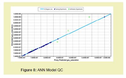
Figure 8 shows the model QC plot for the proxy model. It shows how closely the proxy model predictions match actual values from the simulations. The 45-degree line represents a perfect match between the proxy model and the actual simulation results. The closer the points are to the 45-degree line, the better the match between the predicted and actual data. Since majority of the points fall on the 45-degree line it indicates that the simulation model was perfectly predicted. Despite this, there were some outliers, indicated by points that were a little farther from the 45-degree line. The statistics of the Radial Basis Function Neural Network Model can be seen in Table 3. A training R2 value of 0.999 and a testing value of 0.792 indicates a strong relationship between the proxy model built and the actual simulation. Hence, the results obtained from the sensitivity analysis can be relied upon.

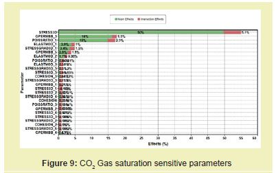
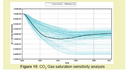
Figures 9 and 10 show the impact of the sensitive parameters investigated on the amount of CO2 gas saturation that leaks. It can be seen from Figure 9 that the most impactful parameter is the effective stress followed by the grid permeability in the fracture with 50% and 16%, respectively. These are indicative of the importance of moderating these parameters to avoid caprock failure. One means by which this can be achieved is to make sure the injection pressure is kept below the reservoir fracture pressure. This would allow the safe capture of CO2 for ages without the risk of leakage. As seen in Figure 10, maintaining an eye on these parameters has the ability to reduce the amount of CO2 leakage and thereby increasing the chances of a sustainable oil and gas future.
This study has shown through numerical simulation how a CCUS operation can be effectively optimised for a greener tomorrow. The work looked at the various trapping mechanisms, modelled the fracture failure, and run sensitivity analysis using RBF controlled proxy model. The following are some key conclusions from this study:
- a. The presence of a Caprock is integral to preventing the migration of captured CO2.
- b. Incorporating a structural trapping mechanism alone resulted in 19.84% of CO2 entrapment. However, residual trapping contributed to 78.71% and solubility trapping leading to 60.98% entrapment.
- c. Despite the increment in trapping offered by the three main trapping mechanisms, having a caprock significantly reduced the CO2 leakage.
- d. CO2 leakage through caprock is mostly influenced by the fracture effective stress. Hence, the need to always monitor injection pressure since it can increase the stress.
None.
This Research Article received no external funding.
Regarding the publication of this article, the authors declare that they have no conflict of interest.

