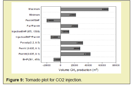
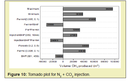
Methane gas hydrate is a solid inclusion compound composed of gas and water, which is stable under high pressure and low temperature. However, the required natural gas exploration method is different from the usual traditional gas reservoir development. The exchange of methane with carbon dioxide is a leading unconventional technology for the production of natural gas hydrate. The production process of methane gas hydrate is simulated by using CMG STAR reservoir simulation software. The ability of CH4 in hydrate exchanged by injected CO2 gas and CO2-N2 mixed gas is compared, and the exchange situation of CO2-CH4 is evaluated. The results show that carbon dioxide injected into the process of methane hydrate formation has the ability to seal carbon dioxide in the form of carbon dioxide hydrate while recovering methane. A mixture of 78% nitrogen and 22% carbon dioxide produces 76.7% methane, while methane using only carbon dioxide produces 61%. Methane recovery increases with the increase of reservoir temperature and permeability. CH4-CO2 exchange technology through gas injection into hydrate reservoirs is feasible in practical oilfields, and natural gas production can be increased by injecting a mixture of nitrogen and carbon dioxide.
Keywords: Methane gas hydrate, Gas injection, CH4–CO2 exchange, Quantitative analysis, Numerical simulation
Natural gas approaches recovery zones via pressure gradients in conventional gas reservoirs. In such reservoirs, the rate of gas production depends on permeability of the formation and also the pressure gradients between the reservoir and production well(s).1-3 Exploration and production of gas from hydrate-bearing reservoirs require an additional energy to dissociate the crystalline water lattice that makes up the structure of the hydrate. Various methods have been suggested for producing methane gas from hydrate deposits, thermal stimulation, depressurization, chemical injection of inhibitors and CO2 or mixed CO2 and N2 exchange.4-6
Visual experiments of the dissociation process in glass micro-models illustrated that the hydrate becomes colloidal and migrates with the injected brine during dissociation process.7 Tang and Kotov8 made a conclusion that lower injection rates and temperatures result in higher recovery energy ratios, so does higher initial hydrate saturations. Komai.9 observed that more than 90% of CH4 in hydrate phase can be exchanged by CO2 within 12 hours in their experiment conducted. Panter proved that raising the amount of N2 in gas phase of N2 + CH4 hydrate system, shifts the equilibrium phase boundary to lower temperature and higher-pressure conditions.10
Ohgaki. observed that fraction of mole of CO2 in hydrate phase was higher than those in gas phase during the process of exchange.11 Seo quantified this observation by revealing that gas phase mole fractions of the hydrate formers (i.e., CH4 and CO2) above 40% CO2 gave hydrate phase fractions of mole of CO2 in hydrate phase higher than 90%.12 Minagawa proposed the idea of electrical heating assisted depressurization technology.13 Gupta of India Dhanbad Production University proposed the CO2 swapping assisted depressurization technology in an attempt to ensure an environmentally friendly production of CH4.14 Yuan conducted an experiment on hydrate-bearing sediment samples to look into conditions that favors the production of methane from gas hydrate reservoirs with gaseous CO2.15 In experiments performed by Ota. the system temperature and pressure are set to 275K and 3.30MPa respectively.16 These are similar to the figures in the experiments of Yuan.15
In this paper, simulation studies which model unconventional methane gas hydrate recovery methods such as CO2 injection, N2 + CO2 gas injection methods and CH4-CO2 replacement technology is conducted. It is also to compare the injection of appropriate gaseous phase mixtures (of CO2 and N2) as opposed to pure CO2 injection and deduce its effect on the behavior of the reservoir rock for successful CO2-CH2 swapping.
Computer Modeling Group’s CMG STARS reservoir simulation software was selected to conduct the simulation study in this thesis. Establishment of the model was done by referring to the reservoir and operation parameters of Ignik Sikumi Field production trial. The injected gas used is a mixture of CO2 and N2. The method adopted was the depressurization injection from a single well to demonstrate the CO2-CH4 exchange concept. The simulation involved the injection of on CO2 gas and then injection of a mixture of N2 and CO2 gas into the reservoir for CH4 production.
Assumptions
In carrying out the simulation, several assumptions were made which included
- 1. The reservoir is uniform, homogenous and can be represented by a series of cells
- 2. Hydrates that exist in the reservoir are pure CH4 hydrates
- 3. Hydrate exists in equilibrium with excess water
- 4. The system is adiabatic and transfer of heat to and from confining strata is not necessary
- 5. The influence of gravity can be ignored
- 6. Movement of mass is limited to only liquid and gas. Solids cannot flow
Energy conservation model
The conservation equations of each component and the energy are shown in equations (1) and (2). For the flowing component (i.e., CH4, CO2, N2 or H2O), the conservation equations are;

Where Vf is the volume of the mobile phases; Vb is the apparent cell volume; µA and µG is the densities of the aqueous and gas phases, respectively; wi and yi are the percentage mass of components in the aqueous and gas phases, respectively; is the number faces of neighboring cells; (A/l)c is the ratio of effective area and distance between the interfaces; kc is the effective permeability at the interface; pAand pG is the the pressures at the aqueous and gas phases, respectively; nt is the number of chemical reactions;snii and sni is the stoichiometric coefficients of the product and reactant of component, respectively; rn is the rate of volumetric reaction; qi is the mass source from the well.

For the equations of energy conservation:
Where Vr is the volume of rock (solid inert matrix, rock grains); cs is the concentration of total solid; Ur is the energy per volume of rock; UA, UG and Us are the energies of the aqueous, gas and solid phases, respectively; HA, HG and Hrn are the enthalpies of the aqueous phase, gas phases and reaction respectively; kc is the effective thermal conductivity at the interface; T is the temperature; qc is the heat source from the injection/production wells.
Permeability model
The reservoir absolute permeability is modeled with respect to the hydrate saturation. In addition, relative permeability of the mobile phase changes with the effective phase saturation. The fluid phase permeability, effective phase saturation and actual phase saturation are defined in equations (3), (4) and (5) respectively:


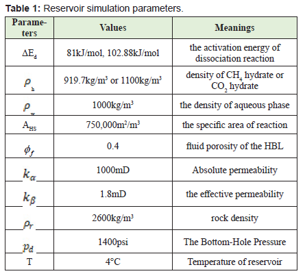
Where ka0 is the reservoir absolute permeability without the presence of the gas hydrate; φ and φf is the reservoir porosity and fluid porosity respectively; m is the model parameter which is set to 4.3413 by changing Civan’s permeability-porosity relationship.17
The flow of the mobile phases follows Darcy’s law, and relative permeability models are revealed in equation (7):

Capillary pressure model
The capillary pressure model of the gas phase and the aqueous phase is shown in equation (8)

Where pc is the capillary pressure; pc0 - model parameter, which is set to 104 Pa and k - model parameter which is set to 0.77437.19
Kim based on experimental results suggested the generally used CH4 hydrate dissociation kinetic model.20 In their model, rate of dissociation corresponded to particle surface area of hydrate and methane fugacity difference at equilibrium and dissociation pressures. When setting the fugacity coefficient, the fugacity can be approximated with an equivalent pressure equal to 1. An assumption was made that formation and dissociation of CH4 hydrate and CO2 hydrate follow the Kim-Bishnoi model. The CH4/CO2 hydrate dissociation rate is expressed as follows:

Where cHyd is the quantity of mole of the CH4/CO2 hydrate per unit volume; k0d is the intrinsic constant rate of dissociation of CH4/CO2 hydrate; AHS is the specific area of reaction, which is 750,000m2/m3 i.e., assuming hydrate particles are regular spheres having diameter of 8lm;21 ρw is the density of aqueous phase, 1000kg/m3; h is the density of CH4 hydrate or CO2 hydrate, 919.7kg/m3 or 1100kg/m3. 22 ΔEd is the activation energy of dissociation reaction, which is 81kJ/mol and 102.88kJ/mol for CH4 hydrate and CO2 hydrate, respectively; R is the gas universal constant; c is the equilibrium pressure; y is the mole fraction of CH4/CO2 in gas phase; K is the equilibrium ratio, as follows,23,24

Where Pg is the gas phase pressure; a1, a2 and a3 are the model parameters and are calculated based on the experimental results of Adisasmito.25
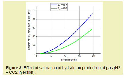
In this paper, simulation and modeling are carried out to understand the process of exchange of CH4 hydrate to CO2 hydrate in the use of CH4-CO2 exchange methods for the production of CH4. The effect of conditions such as reservoir temperature, temperature of injected gas, reservoir pressure including pressure of injected fluid, reservoir hydrate saturation, mole of injected fluid, on CH4 production was studied. This helped understand the various mechanisms involved in the production of gas from hydrates. From this study, the following conclusions were made.
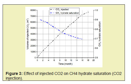
- 1. The direct use of N2+CO2 gas mix instead of pure CO2 shifts the equilibrium phase boundary to lower temperature and higher-pressure conditions and therefore facilitates methane hydrate dissociation. Nitrogen also speeds up the process of depressurization and enhances CO2 exchange. A higher initial mole of gas injected into the system will cause an increase in the driving force of CH4 hydrate dissociation which will yield a higher rate of formation of CO2-CH4 hydrate and subsequently yield a greater CH4 production.
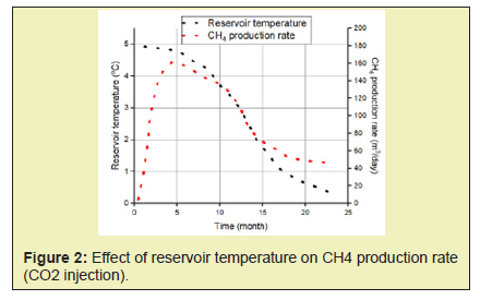
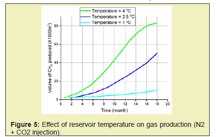
- 2. High temperatures enhance both kinetics and thermodynamics of methane production hence an increase in CH4 production with increase in both the reservoir temperature and the injected gas temperature.
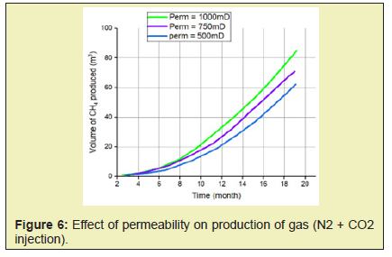
- 3. Permeability controls the flow of both gas and water by influencing pressure propagation in the reservoir therefore higher rates of gas production are associated with a rise in permeability of reservoir.
- 4. During the process of exchange of CH4-CO2 hydrate when low dosage methanol is present, CH4 recovery is enhanced. When methanol is present, formation of hydrate film is delayed at gas–liquid interface enabling additional molecules of CO2 gas to reach the hydrate surface. Higher concentrations CO2 at the surface enables greater diffusion into methane hydrate. Because of the enhancement of the thermodynamic force, more molecules of CO2 are able to replace CH4.
None.
None.
The authors confirms that this article content has no conflict of interest
- 1. Lee S, Liang L, Riestenberg D, et al. Co2 hydrate composite for ocean carbon sequestration. Environmental science & technology. 2003;37(16):3701-3708.
- 2. Smith DH, Seshadri K, Wilder JW. Assessing the thermodynamic feasibility of the conversion of methane hydrate into carbon dioxide hydrate in porous media, in Secondary S Assessing the thermodynamic feasibility of the conversion of methane hydrate into carbon dioxide hydrate in porous media. National Energy Technology Laboratory, Morgantown, WV (United States). 2001.
- 3. Zhou X, Fan S, Liang D, et al. Replacement of methane from quartz sand-bearing hydrate with carbon dioxide-in-water emulsion. Energy & Fuels. 2008;22(3):1759-1764.
- 4. Le TX, Rodts S, Hautemayou D, et al. Kinetics of methane hydrate formation and dissociation in sand sediment. Geomechanics for Energy and the Environment. 2020;23:100103.
- 5. Park Y, Kim DY, Lee JW, et al. Sequestering carbon dioxide into complex structures of naturally occurring gas hydrates. Proceedings of the National Academy of Sciences. 2006;103(34):12690-12694.
- 6. Yamamoto K, Terao Y, Fujii T, et al. Operational overview of the first offshore production test of methane hydrates in the eastern nankai trough. in Offshore Technology Conference. One Petro. 2014.
- 7. Tohidi B, Anderson R, Clennell MB, et al. Visual observation of gas-hydrate formation and dissociation in synthetic porous media by means of glass micromodels. Geology. 2001;29(9):867-870.
- 8. Tang Z, Kotov NA. One‐dimensional assemblies of nanoparticles: Preparation, properties, and promise. Advanced Materials. 2005;17(8):951-962.
- 9. Komai T, Kawamura T, Kang S, et al. In situ observation of gas hydrate behaviour under high pressure by raman spectroscopy. Journal of Physics: Condensed Matter. 2002;14(44):11395.
- 10. Panter JL, Ballard AL, Sum AK, et al. Hydrate plug dissociation via nitrogen purge: Experiments and modeling. Energy & Fuels.2011;25(6):2572-2578.
- 11. Ohgaki K, Takano K, Sangawa H, et al. Methane exploitation by carbon dioxide from gas hydrates—phase equilibria for CO2-CH4 mixed hydrate system. Journal of chemical engineering of Japan. 1996;29(3):478-483.
- 12. Seo YT, Kang SP, Lee H. Experimental determination and thermodynamic modeling of methane and nitrogen hydrates in the presence of thf, propylene oxide, 1, 4-dioxane and acetone. Fluid Phase Equilibria. 2001a.189(1-2):99-110.
- 13. Minagawa H, Ito T, Kimura S, et al. Depressurization and electrical heating of methane hydrate sediment for gas production: Laboratory-scale experiments. Journal of Natural Gas Science and Engineering. 2018;50:147-156.
- 14. Gupta A, Davis M, Kumar A. An integrated assessment framework for the decarbonization of the electricity generation sector. Applied Energy. 2021;288:116634.
- 15. Yuan Q, Sun CY, Yang X, et al. Recovery of methane from hydrate reservoir with gaseous carbon dioxide using a three-dimensional middle-size reactor. Energy. 2012;40(1):47-58.
- 16. Ota M, Abe Y, Watanabe M, et al. Methane recovery from methane hydrate using pressurized co2. Fluid Phase Equilibria. 2005;228:553-559.
- 17. Cai J, Xia Y, Lu C, et al. Creeping microstructure and fractal permeability model of natural gas hydrate reservoir. Marine and Petroleum Geology. 2020;115:104282.
- 18. Singh H, Seol Y, Myshakin EM, Prediction of gas hydrate saturation using machine learning and optimal set of well-logs. Computational Geosciences.2021;25(1):267-283.
- 19. Myshakin EM, Ajayi T, Anderson BJ, et al. Numerical simulations of depressurization-induced gas production from gas hydrates using 3-d heterogeneous models of l-pad, prudhoe bay unit, north slope alaska. Journal of Natural Gas Science and Engineering. 2016;35:1336-1352.
- 20. Kim H, Bishnoi PR, Heidemann RA, et al. Kinetics of methane hydrate decomposition. Chemical engineering science. 1987;42(7):1645-1653.
- 21. Kvamme B, Clarke M. Hydrate phase transition kinetic modeling for nature and industry–where are we and where do we go?. Energies. 2021;14(14):4149.
- 22. Uddin M, Coombe D, Law D, et al. Numerical studies of gas hydrate formation and decomposition in a geological reservoir. Journal of energy resources technology. 2008;130(3).
- 23. Clarke MA, Bishnoi PR. Measuring and modelling the rate of decomposition of gas hydrates formed from mixtures of methane and ethane. Chemical Engineering Science. 2001b;56(16):4715-4724.
- 24. Clarke MA, Bishnoi P. Determination of the intrinsic rate constant and activation energy of co2 gas hydrate decomposition using in-situ particle size analysis. Chemical Engineering Science. 2004;59(14):2983-2993.
- 25. Adisasmito S, Frank RJ, Sloan ED. Hydrates of carbon dioxide and methane mixtures. Journal of Chemical and Engineering Data. 1991;36(1):68-71.
- 26. Chen Y, Gao Y, Chen L, et al. Experimental investigation of the behavior of methane gas hydrates during depressurization-assisted co2 replacement. Journal of Natural Gas Science and Engineering. 2019;61:284-292.


