The in-situ combustion method is the commonly used method for heavy oil production with high recovery rate and low cost. However, the characteristics of the oil oxidation reaction during in-situ combustion are still not clearly understood so far. In this study, the thermal oxidation experiment was carried out for the in-situ combustion process based on the heavy oil from Du 66 block. The results show that: the fired oil zone can be divided into the combustion zone, the coking zone, the condensation zone, the movable oil zone, etc. When the combustion front is formed, the CO2 and CO contents rise to 10% and 20%, respectively. In the expansion phase of the combustion front, the oxygen utilization rate is 83.93%, and the H/C atomic ratio is 1.413, indicating that the high temperature oxidation reaction plays the leading role. Sustained gas injection with enough intensity can ensure that the combustion front moves forward continuously, and the combustion front can drive the crude oil forward in the form of snowballing due to the extremely high oil displacement efficiency. The pressure increases as the combustion front and the movable oil zone advance, but the movable oil zone begins to decrease as it advances to the production well. Through this study, it is concluded that effective combustion front and movement of combustion front are the foundation for the formation of movable oil zone. And the movable oil zone pressurization is an important mechanism for in-situ combustion. The findings of this study can help for better understanding of the in-situ combustion oxidation mechanism and can improve the production design for heavy oil reservoirs.
Keywords: Heavy oil reservoir, In-situ combustion, Oxidation reaction, Characteristics analysis
The methods used in the in-situ combustion mainly include dry combustion and wet combustion.1-4 A large number of experimental and theoretical studies have been carried out on these two combustion methods.5-9 Wilson and Root studied dry forward combustion and forward wet combustion by using lab-experiments. Based on the experiment results, they established relevant calculation formulas and discussed the main influencing factors.10 Chattopadhyay conducted a fire-fighting project on the Santhal oil field. Results show that in-situ combustion can greatly improve the recovery of crude oil, and its recovery is higher than other methods in thermal recovery.11 Rodriguez studied the combustion characteristics of the fired oil layer and the effect of oxygen concentration on the degree of combustion through the indoor sand filling tube burning experiment.12 Chu proposed the method to estimate the minimum air flow needed to maintain combustion.13 Penberthy conducted indoor experiment of dry forward combustion.14 Based on the experimental results, the relationship between temperature and crude oil saturation distribution, material balance, air demand, and oxygen concentration near the combustion front was proposed. Rodriguez studied the advancement of the fire front and the oil displacement characteristics of the fire drive during the fire flooding process.15 Garon conducted an indoor reverse burning test and discussed the influencing factors.16 Greaves proposed the toe-to-heel-air-injection (THAI), a way to use gravity to assist combustion.17 Burger proposed the oxygen demand calculation formula and the ignition time equation and established mathematical models for dry combustion and wet combustion processes.18 Crookston proposed a formula to calculate the combustion reaction rate.19
The combustion characteristics of oxygen-rich conditions were also studied in the in-situ combustion experiments with oxygen-enriched air,20-23 which showed many advantages under oxygen enrichment. The use of thermogravimetric analysis of crude oil cracking combustion theory is not only inexpensive, but also the experimental cycle is short (about one hour).24-26 Many scholars engaged in thermogravimetric analysis under normal and high pressure. The kinetic parameters of crude oil were obtained. The effects of pressure, heating rate, and crude oil properties on reaction kinetics were qualitatively analyzed. Indrijars defined a method of thermal analysis for measuring changes in chemical or physical properties of a sample over time or temperature.27 Although thermal analysis techniques have been widely used in minerals, clays, polymer materials, food, and coal, they have not been used extensively in the petroleum industry. Tadema carried out burning experiments on crude oil and found two different burning areas. These two regions were named as low temperature oxidation and high temperature oxidation, which were carried out at 250°C and 350°C, respectively. In addition, Tadema proposed a method to calculate the air demand for the dry forward combustion process model, and estimated the relationship between recovery factor and the volume of combustion. Later, a large number of scholars used thermal analysis methods to study crude oil combustion. Kok28 analyzed the characteristics of the pyrolysis and combustion properties of two heavy oils. In the cracking test, the temperature range was identified when the viscosity reduction occurred. In the combustion experiment, three different reaction zones were observed, namely low temperature oxidation, crude oil decomposition, high temperature oxidation.
Due to the complexity of the combustion process of the reservoir, it is required to summarize the general rule of in-situ combustion in the oil layer by studying the oxidation reaction mechanism during the fire flooding process. In this paper, the characteristics of oxidation reaction in the fired oil layer of Du 66 fault block in Shuguang Oilfield were studied by combustion experiments. The crude oil and core required for the experiment were taken from the Du 66 fault block in Shuguang Oilfield. The rest of the paper is organized as follows: Section 2 presents the experimental equipment and procedures; Section 3 shows the experimental results; Section 4 is the analysis of most important factors; Section 5 summarizes the entire paper.
Experimental setup
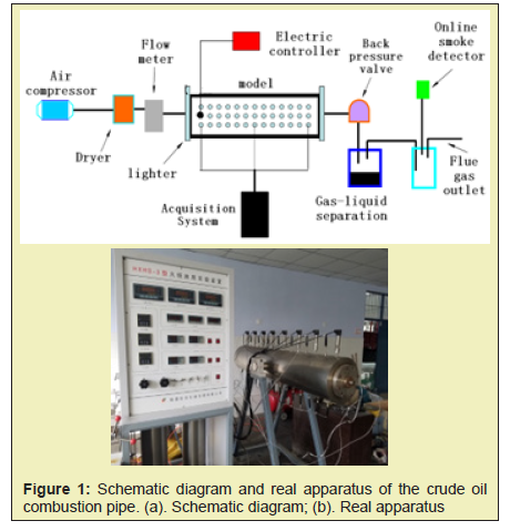
The physical experimental device for in-situ combustion consists of an injection system, a model body, a measurement and control system, and a production system. The injection system includes an air compressor, an injection pump, an intermediate container, a gas cylinder, and a tube valve member. The measurement and control system collects and processes temperature, pressure and the flow signal. The output system mainly completes the separation and measurement of the produced fluid of the model. The schematic diagram and real apparatus of the crude oil combustion pipe is shown in Figure 1. The maximum working temperature of the fireflood physics simulation experiment is 900°C, and the maximum working pressure is 5MPa. The natural core used in the experiment was taken from the Du 66 fault block in Shuguang Oilfield. The porosity is 25% and the permeability is 2000mD. The oil density at 20°C is 0.9g/cm3. The oil viscosity is 2023mPa.s.
Experimental procedure
The experiment process of in situ combustion includes four parts: experimental preparation, model loading, ventilation test, and fireflood experiment.
- Experimental preparation: The preparation work of the fireflood experiment includes: a: designing the porosity, permeability, saturation, and other characteristic parameters according to the geological characteristics of the target reservoir; b: conducting preparation for sensor calibration, simulated well processing, igniter detection, etc.
- Model loading: this procedure includes the installation of simulated well, igniter, and sensor, pressure test of the model system, core loading, saturate oil and water, and etc. For extra heavy oils and super heavy oils, due to the lack of fluidity of the crude oil under formation conditions, it is generally difficult to use the intermediate vessel to directly saturate the oil into the model. Instead, the oil, water and sand are mixed and filled into the model according to the designed ratio.
- Ventilation test: The premise of the fireflood experiment is to pre-establish the flue in the formation to ensure that the exhaust generated by the combustion can be discharged in time. Therefore, before the ignition, nitrogen ventilation is conducted to test the connectivity between the injection and the production wells. During the ventilation test, the initial temperature field inside the model should be established to be similar to the actual conditions of the formation. At the same time of ventilation test, the measurement and control system are debugged and the output system is prepared for connection.
- Fireflood experiment: First, start the igniter to preheat. In general, nitrogen is injected into the model instead of air. The main purpose is to prevent oxidation coking before the oil layer is ignited. Then, gradually increase the nitrogen injection rate until the temperature of a certain area around the ignition well reaches a certain value. Reinject the air to achieve the ignition of the target layer. The whole fireflood experiment process generally includes several stages such as low-speed gas injection ignition, step-by-step speed-up fireflood, stable fireflood, and stop gas injection to end the fire drive. During the experiment, the temperature, pressure, and flow signals of each key node of the model system were monitored by computer in real time. The 3D distribution of the leading edge of the combustion zone was monitored in real time.
Distribution characteristics of fire-burning zone
According to the temperature and post-experiment core analysis, from the gas injection well to the production well, the fired oil zone can be divided into the combustion zone, the combustion front, the coking zone, the condensation zone, the movable oil zone, and the original oil zone. The characteristics of each zone is illustrated as follows:
- Combustion zone: there is almost no crude oil in the core and the oil saturation is less than 2%. The core pores is saturated with the injected air. The sand temperature is high due to large amount of combustion reaction heat retained. Since the seepage resistance of air in the porous medium is very small, almost no pressure drop is measured during the experiment. The pressure in the air chamber in this area is basically consistent with the pressure at the bottom of the gas injection well. Since no crude oil participates in the oxidation reaction, the oxygen concentration in this region is the injection concentration. The temperature gradient is very small.
- Combustion front: also called the combustion zone or fire wall, which is the main area where high temperature oxidation reactions (combustion) occur. The oxidation reaction is most severe in this region, and the oxygen saturation decreases rapidly. The temperature in the zone is the highest, generally above 400°C, and reaches 900°C during the experiment. The temperature change is the most intense at the boundary of the zone, and the temperature gradient is the largest.
- Coking zone: a small area in the leading edge of the combustion zone. In this zone, it can be found that solid lumps present in the core after fire extinguishing and the oil saturation is about 5% to 15%. This area provides fuel for the combustion front. The temperature is second only to the fire wall. In this zone, the cracking reaction dominates. The heavy hydrocarbons are cracked into oil coke and gaseous hydrocarbons. The oil coke is deposited on the sand particles to maintain the forward movement of the combustion front. The movement of gaseous hydrocarbons and superheated steam in front of the combustion front is one of the major oil displacement mechanisms for the in-situ combustion.
- Movable oil zone: the movable oil zone is before the coke zone. The main components of the movable oil zone include: the light crude oil produced by pyrolysis, the original formation crude oil without obvious chemical changes, the water and carbon dioxide produced after combustion, and nitrogen in the air. Due to the high oil saturation in this region, the seepage resistance is large. The temperature in this zone gradually approaches the original formation temperature.
- Cold oil zone: this zone locates in the downstream of the movable oil zone. The oil saturation is basically unchanged. Unlike other methods of replenishing formation energy, flue is present throughout the combustion process. The main function of the flue is to discharge the carbon dioxide and other gases out of the stratum. Otherwise, when the concentration of carbon dioxide reaches a certain level, the fire will be extinguished. From this perspective, the remaining oil zone is formed by the sweep of steam and flue gas.
Kinematics and dynamics characteristics of oxidation reaction
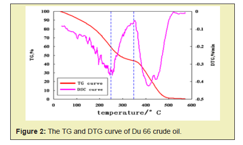
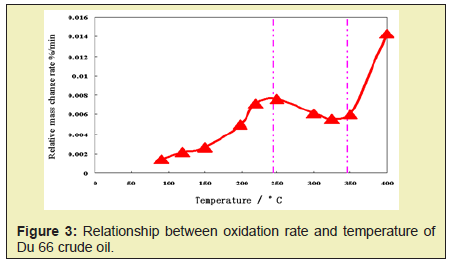
According to the relationship among thermogravimetry (TG), derivative thermogravimetry (DTG), and oxidation rate of different crude oils in air atmosphere, the crude oil temperature range for low temperature oxidation, cracking, and high temperature oxidation is divided. As shown in Figure 2, through the analysis of TG, DTG curve and oxidation rate curve, the temperature range of Du 66 crude oil is divided into low temperature oxidation (<245°C), cracking (245°C ~ 350°C), high temperature oxidation (> 350°C).
In order to better understand the reaction characteristics of the cracking reaction, an analytical experiment under an oxygen-free (nitrogen atmosphere) condition was carried out for the Du 66 crude oil. The crude oil cannot undergo oxidation reaction in the nitrogen atmosphere. As shown in Figure 3, the pressure rises in accordance with the gas state equation when the temperature is lower than 380°C. And the pressure is obviously increased when the temperature is higher than 380°C. This is mainly because there exists hydrocarbon gas generated by the cracking reaction, which results in an increase of the total gas amount in the system. Through the analysis of total hydrocarbon chromatography and group components analysis, it can be found that the cracking leads to the bond cleavage of the crude oil. The macromolecular chain is decomposed into small molecular chains, and the quality of the crude oil is obviously improved.
Stability analysis of the in-situ combustion
1. Characteristics of temperature field
Before starting the igniter, air is injected into the model at a low speed to ensure good internal connectivity. The temperature of the igniter is gradually increased so that the crude oil is fully distilled and cracked at different temperatures and also provides sufficient fuel for oxidative combustion. As shown in Figure 4, the crude oil near the igniter is first ignited, the highest temperature reaches 700°C. The combustion front is formed, and the intense high-temperature oxidation reaction occurs mainly at the combustion front. Large amount of heat is released to ensure the stable expansion of the combustion front. It can be found from Figure 4 that the tendency of the combustion front to expand upward is obvious during the expansion process. This is mainly due to the low gravity of gas. The gas advances faster in the upper part of the model, causing the combustion to overburden.
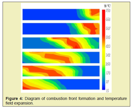
From the temperature field of different stages Figure 4, the temperature contour before and after the combustion zone is the densest and the temperature gradient is the largest. The temperature gradient is small in the area away from the combustion zone. A large range of high temperature zones is formed between the leading edge of the combustion zone and the production well in the late stage of the fireflood. This is mainly due to the steam generated during the evaporation of the original water in the oil layer, which forms a certain degree of steam flooding.
2. Components in the exhaust gas
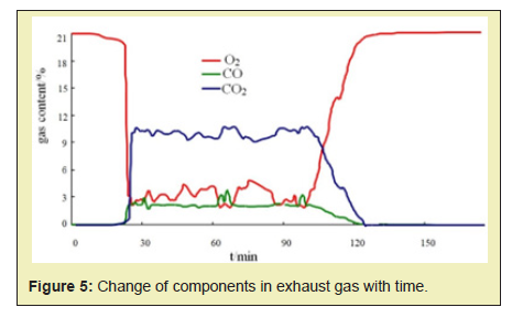
During the experiment, the flue gas analyzer is used to monitor the output of the gas components in the exhaust gas in real time. As shown in Figure 5, when the combustion front is formed, the content of O2 rapidly drops from 21% to about 3%. And the content CO2 and CO rises rapidly, reaching 10% and 2% respectively. During the expansion period of the combustion front, the contents of O2, CO2, and CO were always maintained at a substantially stable state. By calculation, the oxygen utilization rate was 83.93%, and the H/C atomic ratio was 1.413, indicating that the high temperature oxidation reaction was always stable and dominated.
Analysis of movable oil zone formation conditions
1. Effective combustion front
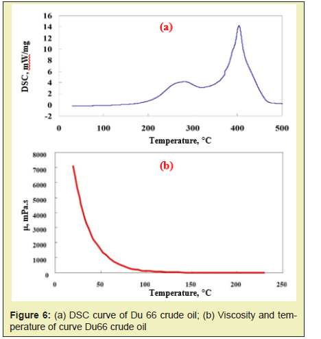
According to the experimental analysis, the threshold temperature of high-temperature oxidation of Du 66 crude oil is 357°C, and the ignition temperature should generally be higher than the threshold temperature of 50°C or more. Therefore, the ignition temperature should be about 407°C or above. Combined with the differential scanning calorimetry (DSC) exothermic curve of Du 66 crude oil Figure 6a, the ignition temperature is located after the peak of the exothermic curve. Therefore, it can form a violent high-temperature oxidation reaction. Large amount of heat can be released and an effective combustion front (the temperature of combustion front is about 500°C~ 600°C) can be formed. Also, it can be found from Figure 6b, the viscosity of the crude oil is greatly reduced by high temperature Figure 6b. It can be concluded that effective combustion front provides a heat source for the formation of movable oil zone.
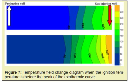
If the ignition temperature is located before the peak of the exothermic curve, that is, it is ignited under 250°C, the low temperature oxidation reaction mainly occurs near the igniter Figure 7. Due to the exothermicity of the low-temperature oxidation reaction, the temperature in some areas is slightly higher than the ignition temperature of 250°C. However, since the crude oil also undergoes a cracking reaction under this temperature condition, the temperature near the igniter is always lower than the threshold temperature due to the endothermic cracking reaction. In the low temperature range, normal high-temperature oxidation reaction cannot be achieved, and this phenomenon continues under the joint action of low-temperature oxidation and cracking reaction Figure 7. With the continuous injection of gas, it carries some heat to the vicinity of the igniter. The temperature continues to expand, but it cannot form an effective combustion front.
2. The movement of combustion front
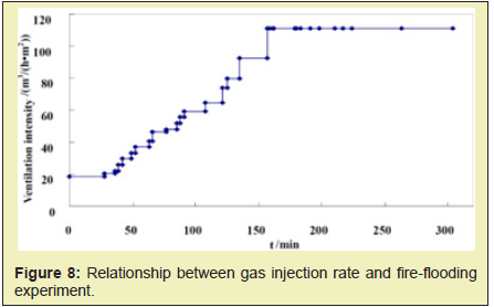
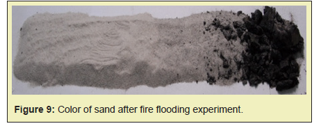
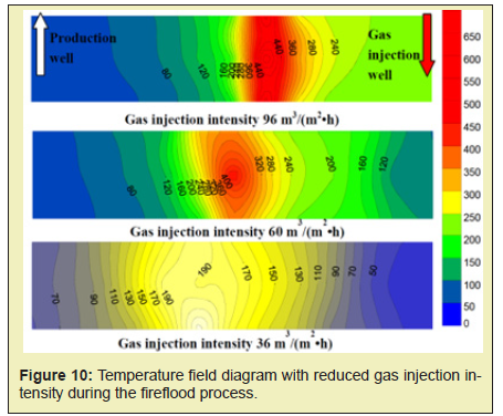
Sustained injection of a certain intensity can ensure that the combustion front moves forward continuously, and the combustion front will drive the crude oil forward in the form of snowballing due to the extremely high oil displacement efficiency. As shown in Figure 8, after the formation of combustion front, the high temperature oxidation can be maintained under the gas injection intensity of 20m3/(m2·h). Due to the formation and aggregation of movable oil zone, the resistance is also increased. The existing gas injection intensity is not sufficient to push the combustion front forward. if the gas injection rate is lowered, the combustion front stops moving, the temperature drops, and the movable oil zone cannot be displaced. Therefore, it is necessary to continuously increase the gas injection intensity and finally the combustion front can be completely advanced in the model direction Figure 9. The experimental results show that the maximum of gas injection intensity can reach 111m3/(m2.h), which is 5.5 times of the initial ignition. The increased gas injection intensity can be considered as the driving force to promote the migration of movable oil zone. Figure 10 shows the temperature field diagram if the gas injection intensity is decreased. As it can be found from Figure 8, when the combustion front moves to the middle of the model, the gas injection intensity is 96m3/(m2.h). It indicates that the movable oil zone is formed. At this time, the gas injection intensity is adjusted to 60m3/(m2.h). As it can be found from Figure 10, the combustion front can maintain high temperature combustion. However, the maximum temperature of combustion and the area of the combustion front shrink constantly, and the move rate of combustion front also begin to decrease. When the gas injection intensity is reduced to 36m3/(m2.h), the highest temperature of the combustion front drops to about 473.15K. The oxidation stage is transfer to low-temperature oxidation Figure 10. The experimental results show that if the gas injection rate is reduced, the combustion front will stop moving and the temperature will decrease. Thus, it will not be able to displace the movable oil zone. It will be difficult to maintain high temperature combustion eventually.
Oil saturation change
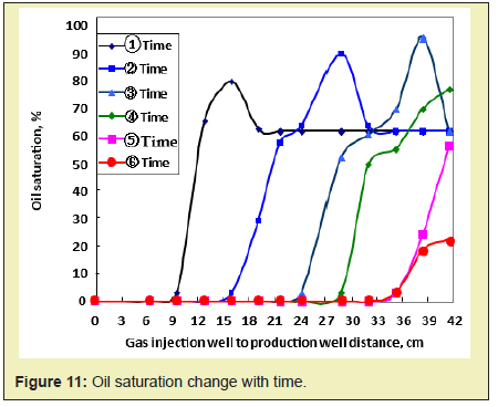
The distribution of oil saturation of movable oil zone in different times is shown in Figure 11. As the combustion front moves (oil saturation is below 10%), the oil saturation gradually increases, which can be up to 85%. The areas with oil saturation above 60% (original oil saturation) gradually increase. As the movable oil zone is constantly produced near the production well, the range of the movable oil zone gradually decreases.
Movable oil zone pressurization
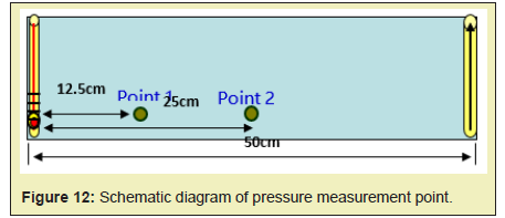
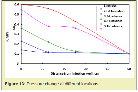
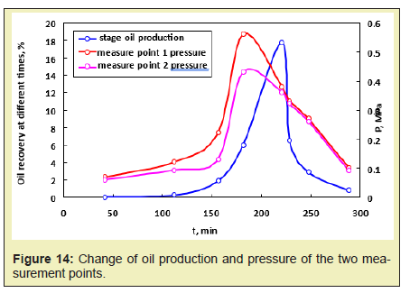
The pressure change in the fire process is detected by arranging different pressure points in the model Figure 12, and the pressurizing mechanism for the movable oil zone can be summarized. During the fireflood process, as the combustion front advances from the injection well to the production well, the pressure gradually decreases. The pressure change at different locations is shown in Figure 13. In the process of fire flooding, the change of pressure and oil production reflects the migration characteristics of removable oil zone: the increase of pressure means that the removable oil zone gradually increases. When the front edge of removable oil zone approaches to the production well, the pressure reaches the peak value and the oil production rate begins to increase. And if the removable oil zone gradually becomes smaller, the pressure also begins to decline and the crude oil production also reaches the peak value. This means that the oil production reaches the maximum value. As it can be found from Figure 13, the overall trend is that the pressure increases as the combustion front and the movable oil zone advance, but the pressure begins to decrease as the movable oil zone advances to the production well Figure 13. When the combustion front is between two pressure measurement points, the pressure difference is greatest. The highest pressure difference is about 0.12MPa. When the combustion front is moving past this point, the pressure difference gradually decreases. After the movable oil zone breaks through the production well, the pressure difference is constant at 0.01MPa. The relationship between oil production and location of pressure measurement point is shown in Figure 14. As it can be found from Figure 14, the pressure and production increase simultaneously. Due to the well position, the pressure peak is prior to the peak of production. The pressure curve shows the peak when the front edge of the movable oil zone is close to the production well. And the production curve shows the peak when the combustion front is close to the production well.
According to the study of this paper, following conclusions can be obtained:
- 1. According to the experimental analysis, the temperature of the condensation zone is the upper temperature limit of the movable oil zone during the fire drive process. And the temperature of the viscosity inflection point is the lower temperature limit of the movable oil zone. Therefore, the upper and lower temperature limits of the movable oil zone can be used to determine the location and thickness of the movable oil zone.
- 2. According to the temperature fields of different stages analysis results, the temperature contour before and after the combustion zone is the densest (4 lines/0.3m) and the temperature gradient is the largest (400°C/0.2m). The temperature gradient is small in the area away from the combustion zone. In the analysis of the exhaust components, when the combustion front is formed, the content of O2 decreases rapidly, and the CO2 and CO contents rise to 10% and 20%, respectively.
- 3. The effective combustion front and the movement of combustion front are the foundation for the formation of movable oil zone. The ignition temperature is located at the peak of the exothermic curve, which can form a violent high-temperature oxidation reaction. It releases a large amount of heat and forms an effective hot line (combustion front temperature of 500°C~600°C). In a certain intensity, sustained gas injection can ensure that the combustion front moves forward continuously, and the combustion front will drive the crude oil forward in the form of snowballing due to the extremely high oil displacement efficiency.
- 4. Through analysis, movable oil zone pressurization is an important mechanism for in-situ combustion. As the combustion front advances from the injection well to the production well, the pressure gradually decreases. The pressure increases as the combustion front and the movable oil zone advance, but the movable oil zone begins to decrease as it advances to the production well. When the front edge of the movable oil zone is close to the production well, the pressure is the highest (0.56MPa) when the combustion front is close to the production well, the oil production is the highest.
The authors acknowledge supports from PetroChina Innovation Foundation: 2019D-5007-0205; and the National Natural Science Foundation of China: No. 51704265.
None.
Authors declare that there is no conflict of interest.
- 1. Kok M. Progress and recent utilization trends in petroleum recovery: steam injection and in-situ combustion. Energy Sources. 2012;34(24):2253-2259.
- 2. Samimi A, Karimi G. In-situ combustion process, one of IOR methods livening the reservoirs. Petroleum & Coal. 2010;52(2):342-354.
- 3. Dong X, Liu H, Chen Z, et al. Enhanced oil recovery techniques for heavy oil and oilsands reservoirs after steam injection. Applied Energy. 2019;239:1190-1211.
- 4. Chanphavong L, Zainal Z. Characterization and challenge of development of producer gas fuel combustor: A review. Journal of the Energy Institute. 2019;92(5):1577-1590.
- 5. Alamatsaz A, Moore G, Mehta S, et al. Analysis of dry, wet and superwet in situ combustion using a novel conical cell experiment. Fuel. 2018;234:482-491.
- 6. Binner E, Zhang L, Li C, et al. In-situ observation of the combustion of air-dried and wet Victorian brown coal. Proceedings of the Combustion Institute. 2011;33(2):1739-1746.
- 7. Yuan S, Jiang H, Shi Y, et al. Study on heavy oil components transformation path based on core analysis during in-situ combustion process. Fuel. 2019;253:72-78.
- 8. Suat B, Mustafa V. In-situ combustion laboratory studies of Turkish heavy oil reservoirs. Fuel Processing Technology. 2001;74(2):65-79.
- 9. Zhao R, Chen Y, Huan R, et al. An experimental investigation of the in-situ combustion behavior of Karamay crude oil. Journal of Petroleum Science and Engineering. 2019;127:82-92.
- 10. Wilson L, Root P. Cost Comparison of Reservoir Heating Using Steam and Air. JPT. 1966:233-239.
- 11. Chattopadhyay S. Enhanced Oil Recovery by In situ combustion Process in Santhal Field of Cambay Basin,Mehsanaay. Gujarat,India-A Case Study.SPE89451. 2004.
- 12. Rodriguez J. Experimental and analytical study to model temperature profile sand stoichiometry in oxygen-enriched in-situ combustion. USA: Texas A&M University, 2004.
- 13. Chu C. State-of-the-art Review of Fireflood Field Projects. JPT. 1982;19-36.
- 14. Penberthy WL, Ramey HJ. Design and Operation of Laboratory Combustion Tubes, SPE1290. 1966.
- 15. Rodriguez M. Near Wellbore and Reservoir Effects In situ combustion. SPE174351-MS. 2015.
- 16. Garon A. A Laboratory Investigation of Sweep during Oxygen and Air Fire flooding. SPE Reservoir Evaluation. 1986;11:845-854.
- 17. Greaves M, Xia T, Turta A, et al. A ‘Short-Distance Displacement’ In Situ Combustion Process for the Recovery and Upgrading of Heavy Oil. Chemical Engineering Research and Design. 2003;81(3):295-304.
- 18. Burger J. Laboratory research on wet combustion. Journal of Petroleum Technology. 1993; 25(10):1130-1136.
- 19. Crookston R, Culham W, Chen W. A Numerical Simulation Model for Thermal Recovery Process. SPE Journal. 1979;19:37-58.
- 20. Petit H. In-situ combustion experiments with oxygen-enriched air. In Situ: Oil Coal Shale Minerals. 1990;14(1):49-76.
- 21. Younes M, Jamal A, Niass T, et al. Oil Heavy Residues Oxy-combustion with CO2 Capture. Energy Procedia. 2017;114:505-521.
- 22. Can R, Tõnis M, Andres T, et al. Oxy-fuel Combustion of Estonian Oil Shale: Kinetics and Modeling. Energy Procedia. 2016;86:124-133.
- 23. Wawrzyńczak D, Panowski M, Majchrzak I. Possibilities of CO2 purification coming from oxy-combustion for enhanced oil recovery and storage purposes by adsorption method on activated carbon. Energy. 2019;180:787-796.
- 24. Pulikesi M, Nader M. Thilakavathi M, et al. Pyrolysis and combustion kinetics of Fosterton oil using thermogravimetric analysis. Fuel. 2009;88(9):1708-1713.
- 25. Yuan S, Zhao L, Jiang H, et al. Reaction schemes and characteristics in crude oil oxidation process using a TGA testing method. Fuel. 2018;234:604-608.
- 26. Abdul G, Han Y, Omar B, et al. Heavy fuel oil pyrolysis and combustion: Kinetics and evolved gases investigated by TGA-FTIR. Journal of Analytical and Applied Pyrolysis. 2017;127:183-195.
- 27. Indrijarso S, Oklany S, Millington A, et al. Thermogravimetric studies of systems pertinent to the in-situ combustion process for enhanced oil recovery. Thermochimica Acta. 1996;277:41-52.
- 28. Kok M. Characterization of medium and heavy crude oils using thermal analysis techniques. Fuel Proces Tech. 2011;92(5):1026-1031.

