Well control is an extremely critical operation that requires a lot of good planning and professional implementation. The selection of the proper kill method that is required to kill the well safely and efficiently either drilling or production well is a tedious decision. It requires a lot of accurate data from the current well conditions which will help the decision makers in their selections. Selecting the wrong kill method may end up with an unsafe and a high costly operation. This paper introduces an excel sheet program to select optimum well kill method that will help the engineering team as well as the operation team to take the proper decision regarding the optimum well control method to be applied.
This paper provide a program built using simple excel sheet in which input data are well information. This information is analyzed and used to answer some questions. The answers for these questions have different weights. The system will select the highest score for these answers which will choose the optimum kill method based on the input data and the weighted value and provide kill sheet for the well according to the selected method.
The program is tested in two different cases for drilling oil and gas wells. The system selected different kill methods based on each well criteria. The outputs were compared with a commercial simulator and the results are comparable which indicate that such a cheap excel program can be used easily and economically.
The main objective of any drilling program is to help assure a well to be drilled, completed, and produced safely economically and efficiently. Due to the complications that are added to the drilling and production processes, a lot of challenges are caused to the operation. A lot of blowouts have been caused because of not following the proper kill method or the proper procedures. These blowouts caused a lot of fatalities, loss of rigs, loss of equipment, damage to environment and loss of production. Recent blowouts and well known in the industry are the blowout happened in the Gulf of Mexico in 2010 (Macondo well) and the blowout happened in Temsah field in 2004.1
Well Control in drilling wells may be controlled by different kill methods. Each method has different applications. The Driller’s method is preferred if the kick size is lower than the kick tolerance volume, deviated and horizontal wells, the string is on bottom, and in case of gas migration where the kill mud is not ready. The wait and weight method is preferred if the kick size is within the kick tolerance calculations, no gas migration is encountered, vertical wells where the volume of the string is lower than the volume of the open hole section. The volumetric method is preferred than the other methods in case the drill string is off bottom, drill string washout, gas migration, hole pack off, totally plugged string or no string is in the well bore. After the volumetric method, lubricate and bleed method has to be used to get rid of the gas. The stripping operation is preferred if the string is off bottom, and the gas is not migrating, and the gas volume is within the kick tolerance calculations. And in case of gas migration, the combined volumetric and stripping operation can be used.
The selection of the proper kill method is challenging and will depend on a lot of factors. These factors are necessary to help and guide the operation team to select the required kill method. However, it will be a critical decision as it will require the knowledge of the different conditions currently in the well. Commercial software are introduced to the industry, but they offer the calculation of the kill sheet and steps to be followed and amount to be monitored during applying the selected technique. Therefore, the need for computerized program to select the optimum method quickly and efficiently is obviously interested for the industry that will help the operation team to select the proper kill method to bring well back under primary control condition as well as the kell sheet calculations.
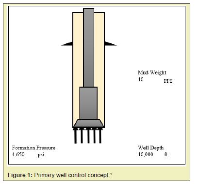
The flow of the formation fluid from the formation into the wellbore is called “kick”. It is also called “influx” if the well still overbalance. If the kick is not controlled, it may led to a blowout. Well control procedures are intended to safely prevent or handle kicks and reestablish primary well control conditions by regaining the hydrostatic overbalance of the mud. During the drilling operation, well control barriers should be in place to control the well. The primary well control barrier during conventional drilling is the hydrostatic pressure of the mud that provides overbalance on the formation being drilled which prevents formation fluid flowing into the well. For example, as shown in Figure 1, if the hydrostatic pressure is 5,200psi at 10,000ft (10.0ppg mud) and the pore pressure is 4,650psi. The difference between the hydrostatic and pore pressure is 550psi; so, the well will be static, and this state is identified as overbalance condition. To control the well, the well should be overbalanced, and this to be planed based on each company policy.2
An overbalance should be maintained during the drilling and tripping operation. The value of the overbalance depends on company policy (normally in a range between 100 to 300psi). If the hydrostatic pressure fails to maintain the overbalance and fails to prevent formation fluids from entering the wellbore, the well will flow and kick is occurred. This process is stopped using the secondary barrier which is the blow out preventers (BOP) to prevent the escape of the wellbore fluids from the well. This is the first stage of the secondary well control. BOP should be tested regularly as per API and/or company policy to make sure that its reliability in case of any well kick and control operations. If the formation cannot be controlled by the primary or secondary well control, tertiary well control will be considered as the third line of defense. Drilling a relief well is considered one of the tertiary well control processes.2-11
In order to implement plan, drill and complete the well safely, it is necessary to have some knowledge of the fracture pressures of the formations to be encountered. The maximum kick size to the wellbore depends on some factors, these factors are the kick intensity “KI” and the fracture pressure of the weakest formation in the wellbore.2
If the wellbore pressure (hydrostatic pressure) is equal to or exceed this fracture pressure, the formation would break down as induced fracture would be initiated, followed by loss of mud, loss of hydrostatic pressure and loss of the primary control. Fracture pressure is a function of the weight of the formation matrix and the fluids occupying the pore space within the matrix, overburden pressure of the formations above the zone of interest. These three factors are combined to produce what is known as the fracture pressure.1-10
In onshore locations, since the sediments tend to be more compacted, the overburden gradient can be taken as being close to 1.0psi/ft. While in offshore, the overburden gradients at shallow depths will be much less than 1.0psi/ft due to the effect of the seawater depth and the large thicknesses of unconsolidated sediment. This makes surface casing seals in offshore wells much vulnerable to breakdown and is the reason why shallow gas kicks is difficult to be shut in.2
Maximum Allowable Annular Surface Pressure (MAASP)
The formation strength normally determined from the leak-off test below the casing shoe using the following Equation 1. MAASP is the maximum allowable annular surface pressure that can be tolerated before the formation at the shoe tend to fracture. MAASP can be determined using one of the following Equations (Equations 2, 3 or 4). It is only valid if the casing is full of the original mud, if the mud weight inside the casing is changed, MAASP must be recalculated. The calculated MAASP is no longer valid if the influx fluids enter into the casing.3
PF@shoe = Ps + Ph@shoe 1
MAASP = PF@shoe– Ph@shoe 2
MAASP = (FG – MG) x TVD Shoe 3
MAASP = (MAMW – MWcurrent) x 0.052 x TVD Shoe 4
Kick Tolerance
Kick tolerance can be defined as the maximum kick size at a certain kick intensity that the well can be safely shut in and circulated out of the well without fracturing the formation at the weakest point in the open hole. In critical sections, it is important to calculate kick tolerance on a regular basis. A lot of factors can affect the kick tolerance size. These factors are the mud density, the bottom hole assembly, the hole depth, the pore pressure, the type of the kick, etc.5
The drilling engineer must calculate the volume of gas influx that can be safely shut in and circulated to the previous casing shoe for each open hole section. These calculations should consider the maximum expected pore pressure, and this will be used to calculate the maximum kick size. The worst-case scenario for a kick occurring is at the greatest depth – when the next casing point has been changed (section TD). To determine the minimum shoe strength required to reach this, some assumptions are made. For a development well, assume that the kicking formation may have a pore pressure equal to the virgin pressure of the first well drilled in that field. During this study the formation pressure is driven from the SIDPP and the hydrostatic pressure inside the drill string. Once the fracture gradient is known, calculate the maximum gas influx volume at the next casing point (section TD).4
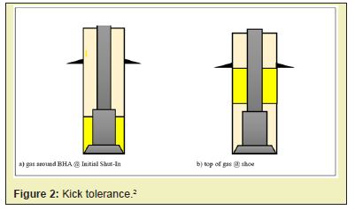
To calculate the kick tolerance, Engineering or operation engineers have to calculate the maximum kick length which may be encountered at initial shut in or when the top of the gas is at the shoe. This length can be calculated using Equation 6. Then they have to convert the length calculated in the previous step into volume. This volume will be calculated two times, one time around the BHA and the second around the drill pipe below the casing shoe. Using Boyles law in Equation 7, will help to convert the calculated volume at shoe into the downhole condition assuming constant temperature and ideal gas.4
![]() 6
6
P1 x V1 = P2 x V2 7
V1 = LMaxx CDPOH 8
At initial shut-in,
V1 = LMax x C BHA&OH 9
Note: Kick Tolerance will be the smaller of the two volumes (V2 calculated from Equation 7 and V1 calculated from Equation 9).
As shown in Figure 2, two scenarios that will give the maximum shoe pressure. The maximum shoe pressure will be either at initial shut-In Figure 2a as the gas will be around the drill collars taking high length, or when the gas is at the shoe of the last casing string Figure 2b where it will take a different length due to the gas expansion. As mentioned in the previous paragraph, it is recommended to calculate the two lengths and then calculate the gas volume in each case, then compare the initial volumes in each case and the lowest volume will be the kick tolerance volume.9
Kick tolerance will always be calculated at the well design stage as it is one of the drivers towards the selection of casing seat and casing specifications. The company policy should be followed before the acceptance of the drilling program and before the drilling operation.3
There are a lot of causes that may end up with a well control situation due to the loss of the overbalance situation. These causes can include, and are not limited to, improper hole filling during tripping out of the hole, swabbing during the pipe movement, loss of circulation, the usage of insufficient mud weight, drilling through abnormal formation pressure, and some other special operations like Drill Stem testing, drilling into an adjacent well and/or excessive drilling rate through a gas sand. Surveys in the past have shown that the major portion of well control problems have occurred during tripping. This is due to reduction in the BHP due to; diminishing of annular pressure loss with pumps off, drop in the annulus levels when pulling the drill string out of hole and not filling the hole with the proper displacement and/or, due to swabbing effect.2-9
The pressure differential between the formations and wellbore, degree of underbalance, is proportional to the influx flow rate and kick volume for a given flow period. The situation can only deteriorate with time because the less-dense formation-fluid volume enters the hole and reduces the buttonhole pressure and thereby serves to increase flow rate into the well. Permeability is another significant factor as well as exposed thickness and fluid viscosity. It is difficult to control permeability or reservoir fluid properties, but the amount of exposed rock is governed by how long the driller continue to drill with kick entry. Gas influx in the well can be expected using the following equation and depends on the exposure time.4
![]() 5
5
Insufficient mud weight is the main cause of underbalance and eventually kicks while drilling. The ECD is considered one of the causes that may end up with well control situation. If the ECD exceeded the formation fracture pressure, downhole losses will occur and cause the fluid level to drop resulting in the reduction of the hydrostatic pressure above the formation and initiating underbalance. If the well becomes underbalanced, it will start to flow and kick generates. The ECD may increases due to increase in the mud weight, increase in the mud rheology, small annular clearance between the bottom hole assembly size and the open hole diameter, increase in the pumping rate, increase in depth or due to increase in ROP and loading the annulus with cuttings. Proper planning should be in place to make sure to drill different formations within the same mud window and to control the mud weight and ECD as planned. Failure to prevent such kicks often leads to underground blowouts.8
Kick IndicatorsDuring the normal drilling or tripping operation, operating parameters should be recorded and analyzed for any anomalies. Kick warning signs are considered some of these anomalies. Observing the warning signs will help to secure the well in case of kicks or even it will reduce the kick size as low as possible. The warning signs can vary from one situation to another. The warning signs are summarized as following: increase in rate of penetration, increase in torque and drag trends, decrease in shale density that can be captured from the downhole logs, changes in mud property, changes in cuttings size and shape, increase in the trip gases, increase in the connection and/or background gas during drilling, increase in the temperature of the return drilling mud and/or, decrease in D-exponent. The observation of positive indicators is a clear message that the well is underbalance and a kick is in progress. Positive indicators are increase in the return flow percentage, increase in the active tank volume and/or flow while pumps are off. The right decision to the observation of any of the positive indicators is to check for flow. If well flow while the pump is off, shut in the well using the proper shut-in procedures as per the company policy. After that choose the kill method and start performing killing procedures.10-19
Kick BehaviorWell kick may consist of water, oil, gas or any combination of them. The mud weight is usually heavier than the kick. The killing operation should proceed to remove the kick from the wellbore or pushed back to the formation. 9
Gas InfluxKick types have different compressibility. One of the conditions affecting the wellbore pressure is the kick compressibility. Gas is one type of the expected kick fluids. The gas compressibility is high compared with the other kick fluids, the temperature and pressure affect the gas volume while being circulated out of the wellbore. For example, a well is shut in on 1bbl gas kick at 10,000ft. The current mud weight is 9.0ppg. The BHT is 170 °F. The hydrostatic pressure of the current mud is 4,680psi. If the gas is allowed to expand, its size will increase to 280 barrels at surface under atmospheric conditions (assuming 0.6 specific gravity gas at 80°F and 14.7psi). If that barrel of gas is not allowed to expand in a controlled manner as it is circulated up the well bore, it will nearly maintain its initial pore pressure as it moves up the annulus and may create excessive well bore pressures. This excessive pressure may cause formation fracture resulting in downhole losses, and underground blowout.20-30
In OBM, Gas has high solubility and the kick detection is challenging which requires good training and special awareness of rig crew. The gas will come out of solution when it approaches the bubble point pressure. The gas expansion will be very fast when gas is near to the surface. The main factors affecting the solubility are fluid type, temperature and pressure.2
Well Control ProceduresMany well control procedures have been developed over the past years. The aim of these methods are to bring the well to its original normal case to continue drilling safely, Figure 3. The constant bottom-hole pressure concept was developed in which the total pressures (mud hydrostatic pressure, casing pressure, etc.) at the bottom of the hole would be maintained at a value slightly greater than the formation pressure to prevent further influxes of formation fluids into the wellbore. This concept can be implemented in two ways.9
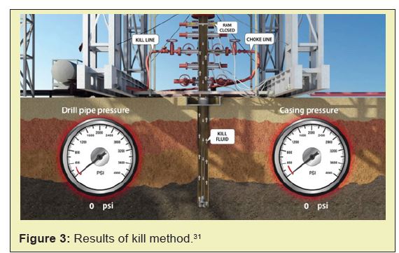
The kill method can be done through one circulation or what is called the Wait and Weight method. After the well has been shut in, the kill mud will be prepared based on the recorded data. A drill pipe pressure schedule should be prepared. The formation fluid and the original mud will be displaced with the kill mud in one circulation. (An alternate name often applied is the engineer’s method). Another method will include two circulations, or what is called the Driller’s Method. The first circulation will be at least bottom’s up and during this circulation the original mud will be used to displace the kick outside the well. The second circulation will be a total cycle which will include displacing the original mud with the kill mud. Both methods will apply a constant BHP which is slightly higher than the pore pressure and named kill circulation methods Figure 2.22
In some cases, Driller’s Method and Wait & Weight method are not applicable. An alternative method should be used based on the well conditions. Unconventional, non-circulation, methods include the volumetric method, Lubricate and bleed method, stripping operation, combined volumetric and stripping operation, and Bullheading.13
Building the excel sheet
During the drilling operation, it is crucial to maintain enough overbalance to keep the formation fluid inside the formation. This can be accomplished by selecting the proper mud weight that will provide the required overbalance. There are a lot of causes that will end up with underbalance situation where the well have to be secured and proceed with the killing operation in order to regain the required overbalance. As mentioned in the previous chapters, there are different types of well control (killing) methods that can be used to regain the primary well control (overbalance).
The selection of the proper killing method is essential to control the well safely and to be able to continue drilling as planned. The selection process for the preferred kill method for drilling operations at different conditions will be justified. This study is based on building an expert system that depend on the advantages and disadvantages of each kill method. The system is built on Excel sheet program.
The Excel sheet program will be mainly based on input data provided by the user. These data will be justified in the form of questions answered by yes or no and based on the actual well data during the well control operation. The program is going to select the proper kill methods based on the input data. The required calculation for the selected kill method will be provided by the sheet program. The user can use this program to control the well and regain the overbalance. It is highly recommended to input all the required data which will help to get the best outputs from the system. The system is divided into inputs that is required from the user and outputs that will be used by the user to control the well.
For the program depends on 12 questions that will be answered based on the input data provided by the user. The weight for each question is generated based on more than 200 trials done on the program and confirmed the optimum weights. The questions need to be answered by Yes or No. These questions are:
- 1. Is the bit on bottom?
- 2. Is circulation valid through drill string?
- 3. Is the well vertical?
- 4. Is the well deviated?
- 5. Is the well horizontal?
- 6. Is the open hole volume les than drill string volume?
- 7. Is the kick gas (gas migration)?
- 8. Is the kick water?
- 9. Is the kick oil?
- 10. Is the Influx volume below kick tolerance?
- 11. Is the kick has a potential of H2S?
- 12. Is the formation has good injectivity?
Program Input
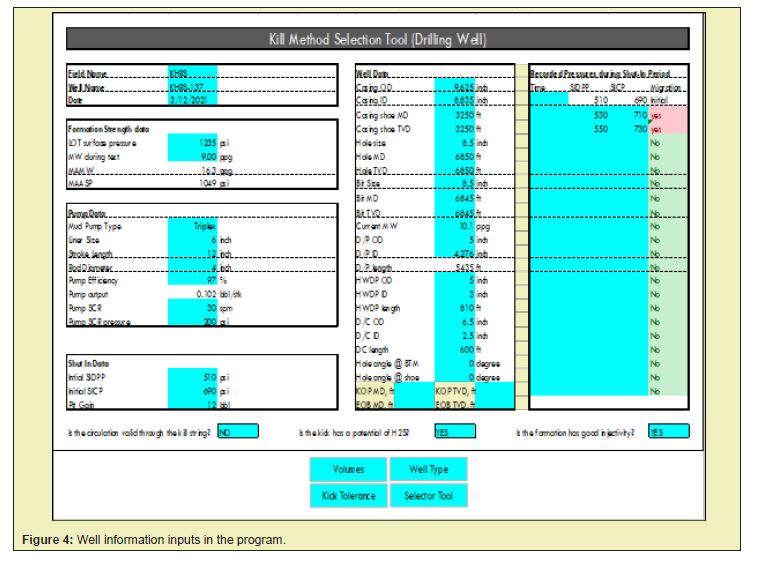
The main input requirements are the existing well data as shown in Figure 4. These information input data includes:
- 1. Field Data
- 2. Formation Strength Data
- 3. Pump Data
- 4. Well Data
- 5. Shut-in Data
The program is going to calculate the well volumes, kick tolerance, kill method selector tool and different calculations for each kill method. The kill methods covered for the drilling wells’ well control are, Driller’s method, Wait and Weight method, Volumetric method, Lubricate and Bleed method, Stripping method, Combined Volumetric and Stripping method and Bullheading method.
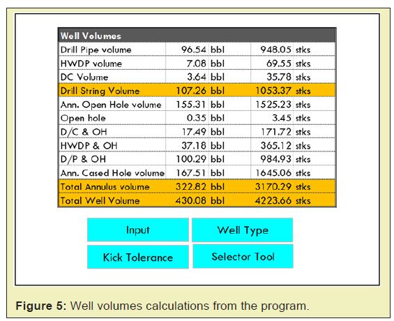
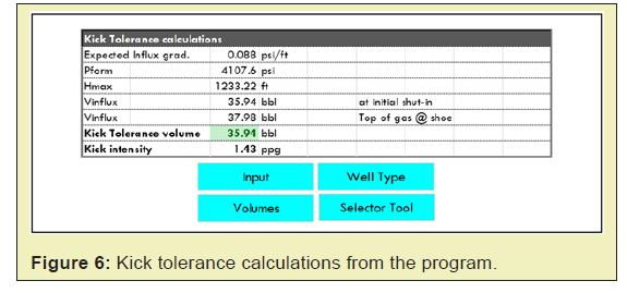
Based on the current string (dimensions and length) and well information, the ESTOK system is going to calculate the different volumes inside the wellbore as shown in Figure 5. The kick tolerance section is going to calculate the maximum allowable kick size based on the current well design, SIDPP and current mud weight. It is going to calculate two values. The first value will be based on the initial shut-in when the kill is around the Bottom Hole Assembly (BHA). The second value will be based on the maximum gas expansion in the open hole and this will be when the top of gas reaches the shoe. The maximum kick size will be the lower of the previous two values. The kick tolerance calculations is shown in Figure 6.
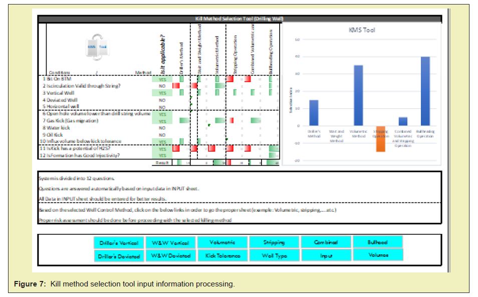
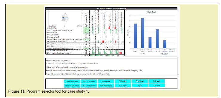
The kill method selector tool section, Figure 7, is going to show the most likely kill method that can be used to kill the well according to the provided data in the input section. This section mainly depends on twelve questions which already captured from the input data. These questions are: is the drill string on bottom? Is circulation valid through the string? Is the well vertical, deviated or horizontal? Is the drill string volume bigger than the open hole volume? Is the kick type gas, oil or water? Is the kick volume below the kick tolerance volume? Is the kick has a potential of H2S? Is the formation has good injectivity? Based on the weight of each question. Each question is answered automatically by yes or no. The program gives a value for each kill method depends on the user input data. The values are summed up for each kill method. The highest score of the answers will determine the optimum kill method.
In the Kill method selection tool section, the user will check the provided graph that shows the maximum selection index as shown in Figure 7. Based on the selected method, the user will click on the proper link for this selected method where the link will direct him to the final calculations for this method. For example, bullheading operation is selected kill method shown in Figure 3.
Program Output
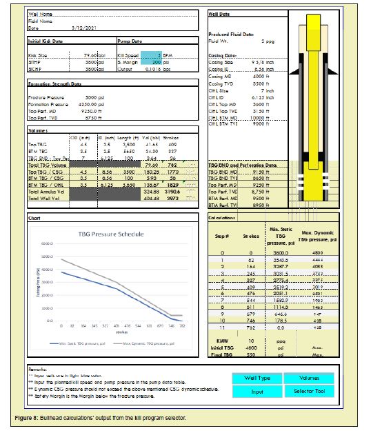
The system will provide the user with the required calculations for the optimum kill method as shown in Figure 8 which is named kill sheet of the well.
The program is applied on tow actual case to validate its results. The following are the results of these two cases studded by the program.
Case Study 1
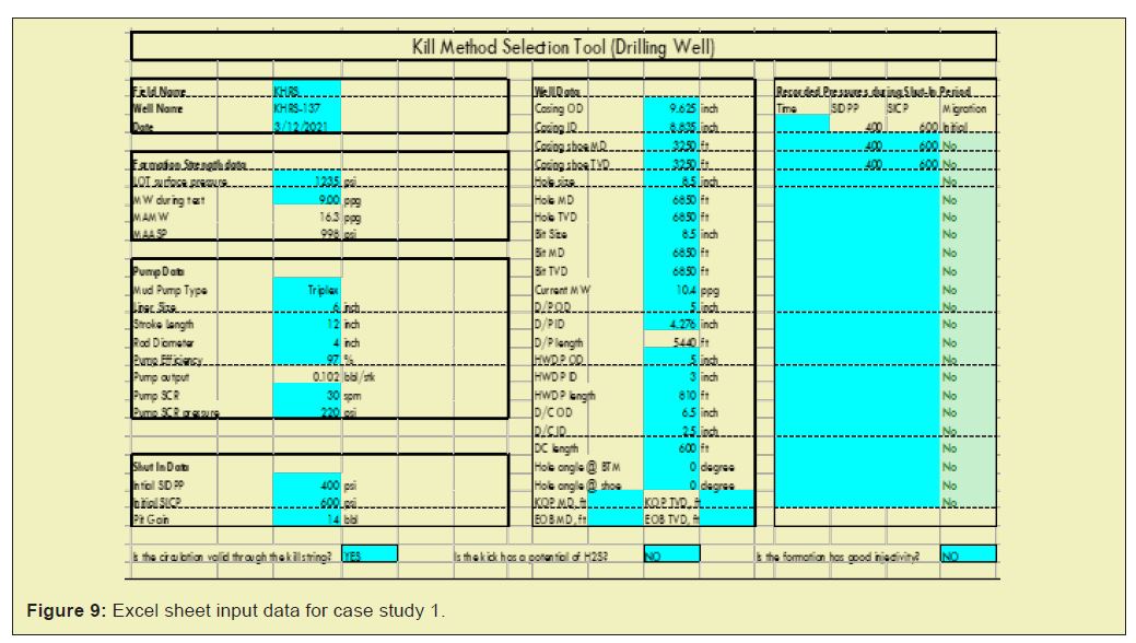
The first well was a vertical well with a total depth of 6,850ft MD/TVD. The 9-5/8” casing was run and cemented at 3,250 ft MD/TVD. A leak-off test was conducted at 3,260ft MD/TVD. The leak-off pressure was 1,235psi with 9ppg mud. The 8-½” hole was drilled with 10.4ppg mud to 6,850ft. A kick was observed during the drilling operation at 6,850ft MD/TVD. The well has been shut-In and the surface pressures were recorded. No gas migration was detected. It was recorded from the offsets that there was no potential of H2S gas during kill operation. The well conditions were inserted in the excel sheet program as shown in Figure 9.
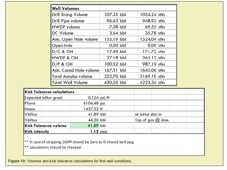
From the program output kick tolerance calculations, the current kick size is within the kick tolerance volume as per Figure 10. The maximum allowable kick size before the casing shoe breakdown was 41 barrels and the kick size was 14 barrels. From the program selector tool, the system recommended to use the wait and weight method as shown in Figure 11 and this was shown in the graph that shows the highest Selection Index. Thus, the Wait and Weight method is the optimum kill method for this case.
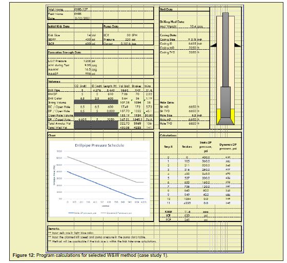
These data were applied on the Drilling and Well Control simulator. The kill sheet of the well is shown in Figure 12 where well data and well drawing, formation pressure strength, volumes, drill pipe schedule and pump strokes table are give on one sheet.
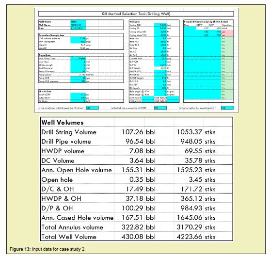
The second well conditions were inserted in the program as shown in Figure 13. The well was drilled to 6,850ft MD/TVD. The 9-5/8” casing was run and cemented at 3,250ft MD/TVD. A kick was observed during the drilling 8-½” hole using 10.1ppg mud. The well has been shut-In and the surface pressures were recorded. Gas migration was recorded. The well was vertical. It was recorded from the offsets that there was no potential of H2S gas during kill operation.
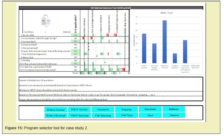
From the program kick tolerance calculations, the recorded kick size was within the kick tolerance volume as shown in Figure 14. The maximum allowable kick size before the casing shoe breakdown was 39 barrels and the kick size was 12 barrels. From the selector tool, the system recommended to use the volumetric method as shown in Figure 15 and this was shown in the graph that shows the highest Selection Index.

The output calculations of the kill sheet shown Figure 16, were applied during killing the well on the simulator as shown in Figure 4,10 and Table 4,2. A safety margin of 50psi and a working pressure of 50psi were used. The SICP was allowed to increase from 690psi to 790psi (SICP plus Safety margin and working pressure) by allowing the gas to migrate. The next step was to allow the gas to expand by bleeding a 4.9bbl mud equivalent to 50psi working pressure while maintaining the SICP pressure constant at 790psi. The next step was to let the casing pressure to increase by working pressure then bled 4.9bbl mud maintaining the casing pressure constant and continue with the same steps until the gas approached surface.
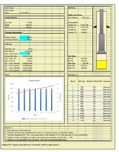
The gas is migrated and expanded safely to surface without any complications related the calculations as shown in the kill sheet.
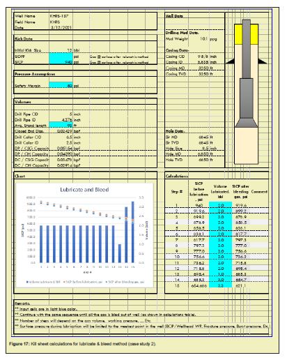
Since volumetric method allows gas kick to migrated and expanded under controlled condition to approach surface, lubricate and bleed method has to be used was used to replace the gas with mud. The program generates a kill sheet for lubricate and bleed method to replace the gas in the well with kill mud, Figure 17.
The program is easy to work with and the results are generated quickly avoiding the wrong decision of the drilling team.
Based on the results obtained from the study the following conclusions are reached:
- Selection criteria for well control methods for both drilling and producing wells are justified based on 12 questions for drilling well and 8 questions for producing well.
- Weighted average for each criteria is given based on 200 well data.
- Excel sheet program is built to select the optimum kill method for drilling or producing wells based on the answers to the selection criteria questions.
- Questions are set as well as input data are identified to be given in the program.
- Based on the input data and the answers, an excel sheet process the data and worked it out, then the optimum kill method is identified through a bar chart.
- Program output give a kill sheet and a kill data for the selected optimum kill method.
- Many runs for the program are processed for the selection of different kill methods.
CDP&OH Annular capacity between drillpipe and open hole, bbl/ft
CBHA&OH Annular capacity between BHA and open hole, bbl/ft
FCP Final Circulation Pressure, psi
FG Fracture Gradient, psi/ft
ICP Initial Circulation Pressure, psi
IG Influx gradient, psi/ft
Kg Gas relative permeability, md
Lk Kick length, ft
Lmax Maximum kick length, ft
MAMW Maximum Allowable Mud Weight, ppg
MASP Maximum Anticipated Surface Pressure, psi
MG Mud Gradient, psi/ft
P1 Formation breakdown pressure at shoe, psi
P2 Formation pressure, psi
PSCR Dynamic pressure loss at slow circulation rate, psi
Pe Pore pressure at the drainage radius, psi
P P Pore Pressure, psi
P F Fracture Pressure, psi
P h Hydrostatic Pressure, psi
P ch1 Choke pressure, psi
P ann Annulus pressure, psi
P W Working pressure, psi
P S Safety margin, psi
P s Applied surface pressure during LOT, psi
P wf Pore Pressure at the wellbore, psi
P Shoe Casing shoe pressure, psi
q gsc Drilled gas entry rate, scf/min
R Gas constant
r e Drainage radius, ft
r w Wellbore radius, ft
stk Strokes
T z Bottomhole temperature, ̊ F
V 1 Kick volume at casing shoe, bbl
V 2 Kick volume at initial shut in, bbl
V k Kick volume, bbl
Z Gas compressibility factor
ΔP / 100 STK Drill String pressure schedule, psi/100 stk
ρ influx Influx gradient, psi/ft
ρ m Mud gradient, psi/ft
μ g Gas viscosity, cp
None.
None.
The author declares no conflicts of interest regarding the publication of this paper.
- 1. Ahmed Elgibaly. Well Control during drilling and workover operations. Journal Management System. 2021;21(1):104-120.
- 2. David Watson. Advanced Well Control”, SPE Textbook Series. 2003;10.
- 3. Robert D. Grace. Advanced Blowout and Well Control”, Gulf Publishing Company, Texas, USA; 1994.
- 4. Shell. Shell Pressure Control Manual for Drilling & Workover Operations. 2002.
- 5. Louis Romo. BP Drilling Well Control Manual. UK. 2000.
- 6. Howard Crumpton. Well Control for Completions and Interventions. 2nd (edn), Gulf Professional Publishing, USA. 2018.
- 7. Neal Adams. Workover Well Control”, PennWell Publishing Company, Tulsa, Oklahoma. 1981.
- 8. Steve Devereux. Practical Well Panning and Drilling”, USA. 2002.
- 9. Well Control School. Guide to Blowout Prevention”, USA. 2002.
- 10. Well Control Research and Development, ASME 2012 31st International Conference on Ocean, Offshore and Arctic Engineering.
- 11. Aberdeen Drilling Schools and Well control training center. Well Control for the Rig-Site Drilling Team Training Manual, Aberdeen, Scotland, and U.K. 2002.
- 12. MAERSK Co. Training Center and Drilling Section. Well Control Training Manual. 2002.
- 13. Adams N. Causes of Underground Blowouts. World Oil. 2006.
- 14. Watson D, Britten ham T, Moore PL. Advanced Well Control. Textbook Series, SPE, Texas. 2003.
- 15. Schubert JJ. Well Control Procedures for the proper Identification and Handling of kicks for the Prevention of Blowouts. Texas A&M University, College Station, Texas. 1995.
- 16. Adam T Burgoyne Jr, Keith K Mulheim, Martin E Cheever, et al. Applied Drilling Engineering, SPE Textbook Series, USA. 1986;2.
- 17. Steven Newman, Adrian Jones. Transocean Well Control Manual, 2004;2.
- 18. Santos OLA. Important Aspects of Well Control for Horizontal Drilling Including Deepwater Situations, Society of Petroleum Engineers SPE/IADC Drilling Conference, Amsterdam, Netherlands. 1991.
- 19. Lloyd GM, Bode DJ, Mickens HV, et al. Practical Application of Real-Time Expert System for Automatic Well Control, Society of Petroleum Engineers SPE/IADC Drilling Conference. 1990.
- 20. Stanislaw Mikolaj, Smith John. Analysis of Alternative Well-Control Methods for Dual-Density Deepwater Drilling. Society of Petroleum Engineers SPE/IADC Drilling Conference. 2006.
- 21. Hornung MR. Kick Prevention, Detection, and Control: Planning and Training Guidelines for Drilling Deep High-Pressure Gas Wells, Society of Petroleum Engineers SPE/IADC Drilling Conference. 1990.
- 22. Speight James G. Formulas and Calculations for Drilling Operations II Well Control, Second Edition. 2018.
- 23. Vega Marcia, Folsta Mauricio Gimenes, Martins Andre Leibsohn, et al. Experimental and Theoretical Study of Control Strategies for Constant Bottomhole Pressure While Drilling Oil Wells, Society of Petroleum Engineers IADC/SPE Managed Pressure Drilling and Underbalanced Operations Conference & Exhibition - Denver, Colorado, USA. 2011.
- 24. Enamul Hossain M, Islam MR. Drilling Engineering Problems and Solutions: A Field Guide for Engineers, USA. 2018.
- 25. Robert F Mitchell, Stefan Z Miska. Fundamentals of Drilling Engineering, SPE Textbook Series, USA. 2011;12.
- 26. Sukumar Laik. Offshore Petroleum Drilling and Production, Florida, USA. 2018.
- 27. Steve Devereux. Practical Well Planning and Drilling Manual, Oklahoma, USA. 1998.
- 28. William C Lyons. Working Guide to Drilling Equipment and Operations, Oxford. 2010.
- 29. Larry W Lake, Robert F Mitchell. Petroleum Engineering Handbook, SPE, USA. 2006;2.
- 30. James G Speight. Handbook of Offshore Oil and Gas Operations, Laramie, Wyoming, USA. 2015.

