Combined Low Salinity Water (LSW) and Alkaline-Surfactant-Polymer (ASP) flooding is a new enhanced oil recovery method that aids oil recovery from reservoirs following the traditional recovery methods. Experimental studies on combined LSW and ASP flooding show additional oil recovery potential. This paper used numerical simulation to investigate different flooding patterns with LSW and ASP combined. A homogenous reservoir was saturated with oil and water to obtain the required modelled factors. Oil reservoir simulations of 11 flooding patterns were created and run using ECLIPSE 100. These patterns were used in the field's development for five years. The results showed the normal 7-spot pattern to provide the best recovery, while the direct line drive provided the worst. The high salinity, low salinity, and combined LSW and ASP flooding recorded oil recoveries of 30%, 55%, and 93%, respectively. An economic analysis was also done to analyse the project’s economic viability which proved to be economical with a profit margin of 40.7%. Furthermore, it was discovered that normal flood patterns outperformed their inverted counterparts. It was thus concluded that the normal 7-spot pattern provides the highest profits from a purely technical standpoint.
Keywords:Alkaline, Low salinity water, Polymer, SurfactantThe rising global energy consumption and a reduction in oil production from fully developed sources have resulted in the development of innovative strategies to meet the demand in a safe, efficient, and cost-effective manner. To recover oil and gas, primary, secondary, and tertiary recovery methods are used.1 When primary and secondary recovery methods are insufficient for prolonged oil production, tertiary recovery methods, also known as enhanced oil recovery methods, must be used. After traditional oil recovery methods render a rising oil saturation immobile, Behnoudfar 2 estimated that the residual oil is nearly two-thirds of the Original Oil In Place (OOIP). According to Speight,3 EOR lowers oil saturation underneath the residual oil saturation (Sor). Sheng1 defined Enhanced Oil Recovery (EOR) as any subsurface process that alters the reservoir's existing oil/brine/rock interactions.
Waterflooding represents the most widespread secondary recovery technique for boosting oil recovery by supplementing the reservoir's natural energy. The possible advantages of waterflooding were first acknowledged in the 1880s with its applications beginning in the 1930s. Waterflooding has since its inception been the most used secondary recovery method of oil recovery through pressure maintenance.4 The water source was typically selected depending on its accessibility, and in the case of offshore oil production, seawater was the obvious choice. The salinity of the injection water was however overlooked.5 Flooding with low salinity water has been shown in studies to improve oil recovery.6 Seecombe7 tested the efficacy of low salinity waterflooding over long inter-well distances in the field. The test was conducted in Alaska's Endicott Field, with an injector and a producer located 1,040 feet apart. After three months of low salinity injection, the water cut decreased from 95% to 92%. Simultaneously, low salinity water broke through. The area swept saw a 10% increase in oil recovery after injecting 1.3 PV. It demonstrated the feasibility of low salinity waterflooding over long inter-well distances. Lager.8 described the successful injection of low salinity brine into an Alaskan reservoir. The observed effect was a significant decrease in the water-oil ratio, accompanied by a doubling of the oil production rate within a year.
In an effort to enhance recovery from hydrocarbon reserves, chemically enhanced oil recovery techniques have been looked into.5 These techniques involve injecting chemicals into the reservoir to boost oil recovery. These chemicals enhance recovery by decreasing the Interfacial Tension (IFT) between the imbibing fluid and the oil, altering the fluid viscosity to improve mobility and conformance control, and altering the wettability of the rock, to increase the oil relative permeability.9,10 Polymer flooding, surfactant flooding, and alkaline flooding are three popular traditional chemical EOR methods.11 Adsorption reduces the efficiency of surfactants and alkalis during flow in porous media. Following that, various modes of chemical flood injections were developed, studied, and applied to EOR processes. These include alkali-surfactant (AS) binary mixtures, Surfactant/Polymer (SP), Alkaline/Polymer (AP), and Alkaline/Surfactant/Polymer (ASP) slugs.10
A surfactant can help recover residual oil by lowering the surface tension between the oil and water phases.12 Low oil-water surface tension lowers capillary pressure, allowing water to displace extra oil.13 If the surface tension can be reduced to zero, then the residual oil can also be reduced to zero. In practice, even high concentrations of residual oil are unlikely to result in the complete recovery of swept zones. Multiple factors influencing the success or failure of a surfactant flood are the proclivity of the surfactant to be adsorbed by the rock. If the adsorption is too high, a large amount of surfactant will be required to produce a little extra oil.13
The primary goal of polymer injection during oil reservoir water flooding is to reduce the mobility of the injected water. This reduction leads to a more favorable fractional flow curve for the injected water, resulting in a more efficient sweep pattern and less viscous fingering.14 Specific plugging effects within highly permeable layers may also occur, causing the injected water to be diverted into less permeable zones of the reservoir. The decreased mobility of the injected water caused by adding polymer has two effects. To begin with, the viscosity of the polymer solution is more significant than pure water (the viscosity of the polymer solution increases as the polymer concentration in the water increases). Secondly, the polymer passage reduces the rock’s permeability to water.13 Specific polymer solutions, such as those of the Polyamide (PA) type, are extremely sensitive to specific salts, and sodium chloride, particularly, can affect viscosity. PA solutions have such unique properties that it is frequently used in highly saline reservoirs. It is necessary to preflush with fresh water to reduce the polymer solution's exposure to the brine from a reservoir.13
Alkaline flooding entails injecting alkaline chemicals (lye or caustic solutions, i.e., high pH solutions) into a reservoir, where they react with petroleum acids to form in-situ surfactants that aid in the release of oil from the rock by reducing interfacial tension, changing the wettability of the rock surface, and causing spontaneous emulsification. Oil can then be transported more quickly through the reservoir to production wells. When the acid content of the reservoir oil is relatively high, alkaline flooding is usually more efficient. Due to its low cost and excellent transport properties in porous media, Na2CO3 is the most popular alkali used. Nonetheless, unless soft brine is employed, the presence of calcium and other divalent cations causes the precipitation of alkalis such as Na2CO3. Zhang15 proposed that NaBO2 should be a replacement for Na2CO3 because it is more divalent ion resistant. Meanwhile, in reservoirs with clay minerals, NaHCO3 is preferable. Finally, because anhydrite (CaSO4) and gypsum (CaSO4.2H2O) precipitate alkali in carbonate reservoirs, sandstone reservoirs are preferable for alkaline flooding. Its synergy with surfactant and polymer in an Alkaline-Surfactant-Polymer (ASP) flooding can reduce surfactant and polymer adsorption on the rock surface, thereby increasing the effectiveness of the surfactant and polymer drive.
The ASP flooding technique employs the injection of alkaline, surfactant, and polymer solutions. Due to the synergy of the constituent components of the injected slug, this technology is widely regarded as the most promising chemical-enhanced oil recovery process.16 The combination of chemicals improves both pore scale and volumetric sweep efficiency. The initial slug contains alkaline and surfactant, which mobilize trapped residual oil in the pore spaces. A polymer slug is then injected to improve the mobility ratio and as a result, the volumetric sweep efficiency.17 Seawater, classified as high salinity water, is used for ASP-EOR, and recent research indicates that changing water's ionic content can change reservoir wettability. A new EOR method emerged by the combination of low salinity waterflood and ASP flood EOR processes for carbonate and sandstone reservoirs. This synergized process maximized oil recovery by utilizing the incremental oil recovery mechanisms of the chemical EOR processes in a synergistic manner.18
Aside from the injection of these chemical flood techniques, the producer-injector flood pattern also has an integral effect on the success of the enhanced oil recovery. Supaprom and Wannakomol19 compared the normal 5-spot and 9-spot water flood patterns in Thailand's Mae Soon Oil Field. The study was conducted using computer simulations with the ECLIPSE Reservoir Simulator, and cost analysis was undertaken. Results from the simulation tests indicated that there is a possibility of oil recovery being increased by approximately 10% to 20%, depending on the water injection rate and water well distributions. It was also discovered that the pattern that gave higher recovery was the 9-spot pattern, which gave a maximum recovery factor of 36.98%.
Broni20 numerical simulation was done with LSW and ASP flooding combined. A heterogeneous reservoir was initially saturated with oil and water, and Eclipse was used. An inverse five-spot pattern was completed, and five years was the assumption made for the reservoir’s production life. The results proved that LSW flooding with a salt concentration of 1000ppm recovered more oil than conventional flooding. The conventional water flooding oil recovery was 59.5%, with low salinity flooding accounting for 64.1%. Overall oil recovery for LSW in combination with alkaline, surfactant, and polymer flooding were 64.1%, 70.5%, and 62.6%, respectively. Overall, the model predicted an increase in overall oil.
Abadli21 simulation study was done to improve total oil production using the ASP flooding method based on the Norne field C-segment simulation model. The black oil model was used for the simulations. First, ASP flooding was simulated and studied for two-dimensional and three-dimensional synthetic models. Polymer flooding, surfactant flooding, surfactant-polymer flooding, alkaline-surfactant and alkaline-surfactant-polymer flooding were considered in the injection process, and actual results from the simulator were analyzed and interpreted.
Hence, this current research work sought to improve the work done by earlier researchers by looking into the effect of various injection patterns on the combined low saline waterflooding ASP. As well as a look into the economic feasibility of the project.
Water flood patterns
According to Tarek,22 one of the first steps in designing a waterflood project is to choose a flood pattern. The goal is to create a pattern allowing the injected water to contact as much of the oil as possible. Converting existing producers to injectors or drilling infill injectors can be used to obtain injectors. Generally, selecting an appropriate flooding pattern depends on the number and location of existing wells. The two main types of suitable arrangements used in fluid injection projects are peripheral and regular injection patterns.
Reservoir description and modelling
Schlumberger Eclipse Software was used to model an oil reservoir in the X, Y, and Z directions, the reservoir measured approximately 150m, 150m, and 84m, respectively. A total of 15,000 grid blocks were used, equating to 50 grid blocks in the X-direction, 50 grid blocks in the Y-direction, and six (6) grid blocks in the Z-direction. This simulation applied flexible grids with precise corner point geometry. The reservoir was homogeneous, with no differences in porosity or permeability. The model's active fluid phases were water and oil. The reservoir is an undersaturated dead oil reservoir with an area of 22,500m2 and is located at a depth of 2,600 metres sub-surface. It has a thickness of 84m and an initial pressure of 270 bar.
Low salinity water flooding modelling
The RUNSPEC keyword BRINE enabled the modelling of mixing waters with varying salinity levels. The aqueous phase concentration of salt alters the density and viscosity of the water. A mass conservation equation for the concentration of the salt in each grid block was used to model the brine distribution. Brine was taken to remain in the aqueous phase and was modeled as a water phase tracer internally using Equation (1)13
![]()
Cs = salt concentration in the aqueous phase
µs eff = effective viscosity of the salt
Dz = cell centre depth
Bw = water formation volume factor
g = acceleration due to gravity
T = transmissibility
PW = water pressure
krw = water relative permeability
Sw = water saturation
V = block pore volume
Qw = water production rate
When modelling the low salinity water flooding, it was assumed that the low salinity water caused formation change in wettability, resulting in a direct change in the fluid’s relative permeability. Eclipse was configured to use the low salinity option. The keyword LOWSALT is found in the RUNSPEC section, allowing for the simulation of low salt water. This configuration allows the saturation and relative permeability endpoints to be changed as a function of salt concentration and oil-water capillary for water and oil phases. As a result, double sets of water/oil saturation functions were used in modelling the simulation. The saturation end points were modeled using double sets of saturation functions, one for low salinity and another for high salinity, as shown in Equations (2) to (5):13
![]() (2)
(2)
![]() (3)
(3)
![]() (4)
(4)
![]() (5)
(5)
where, F1 = function of the salt concentration
Swco = connate water saturation
Swcr = critical water saturation
Swmax = maximum water saturation
Sowcr = critical oil saturation in water
H = high salinity index
L = low salinity index
The F1 factor varies with brine concentration and is available in a form of a look-up table via the LSALTFNC keyword. The water and oil relative permeability, as well as the oil-water capillary pressure, are then determined using a look-up table at the scaled saturations and interpolated in a similar way, as shown in Equations (6) to (8):13
![]() (6)
(6)
![]() (7)
(7)
![]() (8)
(8)
where F2 = the salt concentration function
krw = the water relative permeability
kro = oil's relative permeability
Pcow = oil-water capillary pressure
The LSALTFNC keyword was used with the LOWSALT option to enable input of the weighting factors for the low salinity saturation functions as a function of salt concentration. In the PROPS section, the keyword was enabled. Three columns of data were required for the LSALTFNC keyword: salt concentration and two weighting factors. F1 and F2 represented the deciding factors. F1 was the deciding factor for the interpolation of low salinity saturation endpoints and relative permeabilities, and the deciding factor for the interpolation of low salinity capillary pressure was F2. A value of 0 indicated that only high salinity saturation functions would be applied, while a value of 1 indicated that only low salinity saturation functions would be applied. The deciding factors demonstrated the efficacy of salinity.
Modelling of low salinity and high salinity curves
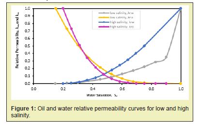
Water and oil were present in the reservoir as active fluid phases. SWOF keyword characterized the input tables of water relative permeability, oil-in-water relative permeability, and water-oil capillary pressure as functions of water saturation in the PROPS section. Thus, every table had four data columns for the high and low salinity relative permeability values. SATNUM keyword was defined in the REGIONS section to specify each grid block's high salinity saturation function table (SWOF). In the REGIONS section, the LWSLTNUM keyword was also defined to specify the low salinity saturation function region to which each grid block belongs. Figure 1 depicts the relative permeability curves for oil and water at high and low salinity as a function of water saturation in the simulation.
The PVTW keyword, characterized in the PROPS section, was used to simulate the PVT properties of water. It was made up of five data records: water formation volume factor at a reference pressure, water compressibility, water viscosity at a reference pressure, reference pressure and water viscosity. The DENSITY keyword was also used to specify the three fluid densities at surface conditions (water, oil, and gas). With the PVT properties of dead oil, the PVDO keyword was used. It had three data columns: the oil phase pressure, oil formation volume factor, and oil viscosity. Furthermore, the ROCK keyword recorded the compressibility of the formation rock at the reference pressure.
Alkaline flooding modellingAlkaline flooding aims at introducing alkaline into the reservoir, where it reacts well with naphthenic acids in situ to produce surfactants, lessening interfacial tension and thus releasing oil from the rock pores. The alkaline injection is usually effective when the oil is acidic. When used in conjunction with surfactant and polymer, as in ASP flooding, alkaline can lessen surfactant and polymer (highly-priced chemicals) adsorption on the rock surface. As a result, alkaline improves surfactant and polymer injection potency.11 This model assumed that alkaline exists as a concentration in the aqueous phase during a water injection process. The ALKALINE keyword was used to activate the alkaline model using Equation (9):13
![]()
where, ρw and ρr = water and rock density, respectively
∑ = sum over neighbouring cells
Ca = alkaline concentration
![]() adsorbed alkaline concentration
adsorbed alkaline concentration
µseff = effective viscosity of the salt
Dz = cell Centre depth
Bw, and Br = water and rock formation volume factor, respectively
T = transmissibility
krw = water relative permeability
Sw = water saturation
V = block pore volume
Qw = water production rate
PW = water pressure
g = acceleration due to gravity
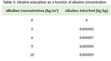
In the PROPS section, alkaline adsorption by rock formation is specified by the ALKADS keyword. The saturated concentration of alkaline adsorbed by the rock formation and the local alkaline concentration in the solution surrounding the rock represent its two columns of data. Instantaneous assumption was made for the adsorption of alkaline. The PROPS section's ALKROCK keyword was employed to determine as to if alkaline desorption was avoided or permitted. The adsorbed alkaline concentration might not have declined over time if desorption had been avoided. It was assumed that the alkaline reaction on polymer or surfactant adsorption was irreversible. The alkaline concentration of the solution would have declined if desorption had been permitted. The alkaline adsorption as a derivative of the alkaline concentration used in this study is shown in Table 1.
Surfactant flooding recovers residual oil through surface-acting agents to adsorb onto the oil-water interface and lessen interfacial tension. Low oil-water interfacial tension lowers capillary pressure, allowing water to displace oil trapped. The effectiveness of the surfactant injection process is influenced by surfactant adsorption by the rock formation. If the adsorption is exceptionally high, a large amount of expensive surfactant will be required to produce a small amount of additional oil.1 By including the keyword SURFACT in the RUNSPEC section, the surfactant model was initiated. The surfactant was assumed to be present solely as a concentration in the aqueous phase. The surfactant injected was modeled in Eclipse by solving a surfactant conservation equation in the aqueous phase.
Surfactant adsorption modellingSurfactant adsorption was taken to be instantaneous in this study, and the adsorbed quantity is a function of the nearby surfactant concentration. The quantity of surfactant adsorbed onto the formation rock was calculated using Equation (10):
![]()
where, PORV = pore volume of the cell
Φ = the porosity
MD = mass density of the rock
CA(Csurf) = adsorption isotherm as a function of local surfactant concentration in solution
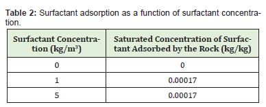
The PROPS section's SURFADS keyword contained surfactant adsorption function tables that characterized surfactant adsorption by the rock formation. It had two columns of information: the local surfactant concentration in the solution surrounding the rock and the saturated surfactant concentration adsorbed by the rock formation. The SURFROCK keyword, which was also found in the PROPS section, was constituted of tables that specified the rock properties needed for the surfactant model. It had two columns of data: the adsorption index for the rock type and the rock type's mass density at reservoir conditions. The adsorption index has two possible values: 1 and 2. If the value 1 is chosen, the surfactant adsorption isotherm is retraced when the local surfactant concentration in the solution decreases. Alternatively, if the value 2 is selected, it implies zero surfactant desorption. SURFADS and SURFROCK data are stated in Tables 2 and 3.

The overall mechanism regarding oil recovery via polymer flooding is as follows
- Increase the viscosity of the water
- Reduce the effective permeability to water as a result of polymer retention
- Reduce the water-oil mobility ratio, which improves sweep efficiency
By specifying POLYMER in the RUNSPEC section, the polymer option was enabled. The keyword BRINE was also activated in this model because salt sensitivity for polymer was required. It was assumed that the flow of the polymer solution through the formation did not affect the flow of the hydrocarbon phase. As a result, the standard black oil equations were used to describe the hydrocarbon phase in the model. Equations (11) to (14) show the water, polymer, and brine equations used in the model:13
![]()
![]()
![]()
![]()
where, Sdpv = the dead pore space within each grid cell
Cap = polymer adsorption concentration
ρr = the mass density of the rock formation
Φ = porosity
ρw = water density
∑= sum over neighbouring cells
Rk= polymer retention's relative permeability reduction factor for aqueous phase
Cp, Cn = the polymer and salt concentrations in the aqueous phase
µgaff = effective viscosity of the water (a = w), polymer (a = p) and salt (a = s)
Dz = cell centre depth
Br, Bw = rock and water formation factor volumes
T = transmissibility
krw = water relative permeability
Sw = water saturation
V= block pore volume
Qw = water production rate
PW = water pressure
g = acceleration due to gravity
The model assumed that the aqueous phase's density and formation volume factor were unaffected by polymer and salt concentrations.
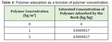
Polymer adsorption modellingThe concentration of adsorbed polymer does not decrease with time if polymer desorption is not allowed. Each grid block retraces the adsorption isotherm as the alkaline concentration in the grid cell increases and falls if polymer desorption is permitted. This effect was specified using the PLY ROCK keyword. The PLYADS keyword in the PROPS section contained tables of polymer adsorption functions that characterised the polymer's adsorption by the rock formation. The table had two columns of data: the saturated polymer concentration adsorbed by the rock formation and the local polymer concentration in the solution surrounding the rock (the mass of adsorbed polymer per unit mass of rock). Table 4 contains the PLYADS data.
The presence of polymer and salt in the solution resulted in a change in the viscosity of the aqueous phase, which was accounted for by viscous terms in the fluid flow equations. The fluid components were assigned practical viscosity values calculated using the Todd-Longstaff technique by incorporating the effects of physical distribution at the leading edge of the slug and fingering at the rear edge of the slug. Equation (15) expresses the effective polymer viscosity as:
![]()
where, µm (Cp) = the viscosity of the thoroughly mixed polymer solution as an increasing function of the polymer concentration in the solution
µp = injected polymer concentration in solution
ω = represents Todd-Longstaff mixing parameter
The mixing parameter aids in simulating the separation of water and injected polymer. In each grid block, if ω = 1, the polymer solution and water are mixed. In contrast, if ω = 0, the polymer is completely isolated from the water. The PLMIXPAR keyword was used to specify the Todd-Longstaff mixing parameter. The SALTNODE keyword consisted of salt concentration value tables, each of which characterized the nodal salt concentration values used to calculate polymer solution viscosity. The PLYVISCS keyword contained tables of polymer viscosity multiplier functions that defined how increasing the concentration of salt and salt in the solution affected pure viscosity.
Polymer and salt concentrations for mixing calculations
The PLYMAX keyword contained information and the data about the maximum polymer and salt concentrations used in the mixing parameter to calculate fluid component viscosities. Simulation procedure for the injection patternsThe work was completed by first developing static and twelve dynamic models based on the static model. The static model served as the reservoir's geological model without any production. Eleven of the dynamic models evaluated represented the flood patterns. The remaining dynamic model was developed to maximise reservoir production without pressure support. It was in charge of the entire project. The following patterns have been evaluated:
- i. Normal 4-spot pattern
- ii. Inverted 4-spot pattern
- iii. Normal 5-spot pattern
- iv. Inverted 5-spot pattern
- v. Normal 7-spot pattern
- vi. Inverted 7-spot pattern
- vii. Normal 9-spot pattern
- viii. Inverted 9-spot pattern
- ix. Direct line drive
- x. Staggered line drive
- xi. Peripheral flood patterns
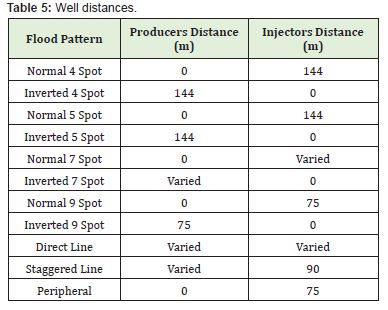
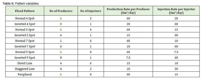
An initial field production and field injection rate of 60sm3/day was used for all flood patterns. Constant values were made for all patterns to produce a clear foundation for comparison and eliminate the possibility of bias. Injectors also started injecting on 1stApril 2021, to help maintain the production profile's plateau. The reservoir pressure has dropped to the point where production will begin to decline on 1st April 2021, resulting from an examination of the control model. Oil production rates were used to control all producers, and water injection rates were used to control all injectors. When the reservoir pressure dropped so low that the required production rate could not be sustained, the producers shifted from oil production to bottom-hole pressure control. The control model analysis also revealed that one well was sufficient to drain the entire reservoir. As a result, each pattern used the fewest number of producers possible. Names of producers begin with the letter “OP” and injector names begin with the letter “INJ”. Wells were named numerically. The well distances used in each pattern are indicated in Table 5. Table 6 shows the number of producers, injectors, production and injection rates per well used in each pattern. All production rates sum up to 60sm3/day, and all injection rates sum up to 60sm3/day in each pattern.
To determine the economic viability of each pattern with the LSWASP project and to provide a baseline for comparison, the total amounts of crude oil produced at the end of the field's life were multiplied by crude and ASP prices. The average cost of drilling and completion of an offshore well and the average cost of a work-over operation were also used. The idea was to calculate the profitability of each pattern by subtracting the cost of execution from the cash inflows generated by hydrocarbon production and sales. The crude oil and ASP prices used were those as of January 14, 2020, as obtained online (www.oil-price.net). Oksol23 provided the price estimates. They had been used for the entire 5-year period. All costs used are shown below:
- i. The average cost of drilling and completing an offshore well =$100 million
- ii. The average cost of a single work over operation = $70,000
- iii. Frequency of work over operations per well = One week per year
- iv. Price of crude Oil = $75.88/bbl
- v. Price of Surfactant = $3.25/bbl
- vi. Price of Alkaline = $1.25/bbl
- vii. Price of Polymer = $2.75/bbl
A simple Microsoft Excel spreadsheet was created to make the required computations.
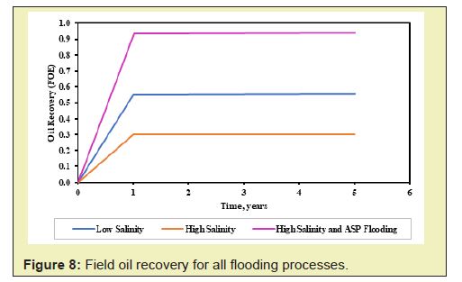
Numerous flooding techniques were tested, including low salinity water, alkaline, surfactant, and polymer flooding. The reservoir's production life was five years. The flooding process began on January 1, 2020, with the first production day. Wellbore diameter was 0.6m, and the reservoir fluid volume rate for both injector and producer wells were set at 60sm3/day. For each flooding process, the Oil Recovery (FOE), Oil Production Rate (FOPR), and Water Cut (FWCT) were plotted. This project again set out to determine the profitability of various water flood patterns. The results are in three forms: the recovery factors (RFs) of the various patterns the profits obtained from each pattern the ASP project viability and the water cuts for the flooding processes.
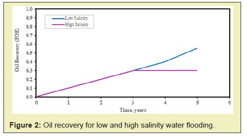
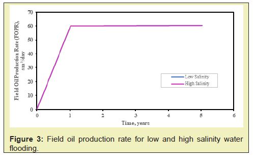
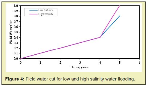
Comparison of results for low and high salinity waterfloodingExperiments have shown that low salinity water flooding improves oil recovery compared to conventional water flooding or high salinity water flooding.24,25 Simulation results of high salinity water flooding with a salinity concentration of 35kg/m3 and low salinity water flooding with a salinity concentration of 1kg/m3 were compared. The FOE, FOPR and FWCT for the flooding process are illustrated in Figures 2-4. The high salinity water flooding yielded an oil recovery factor of 30%, while low salinity water flooding yielded 55%. An increment of 25% due to decreasing the salinity concentration of the injected water was realized. In low salinity water flooding, the wettability change from oil-wet to more water-wet was the significant reason for enhancing oil recovery. Both flooding techniques maintained their oil production rate of 60sm3/day.
The numerical simulation of low salinity water flooding combined with ASP flooding was investigated after studying the singular effect of low and high salinity flooding. Injection was made over the same period for alkaline, surfactant and polymer. The first phase of injection was the low salinity water, which began from the start of production to 180 days. ASP flooding commenced up until five years. Surfactant and polymer were injected following the first injection of alkaline. It was to prevent the adsorption of surfactants on the reservoir rock since it can reduce its surfactant effectiveness. Salt concentration was 1kg/m3. The alkaline, surfactant and polymer concentrations were 20kg/m3 for each. Figures 5 to 7 present the results obtained from the simulation.
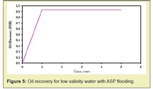
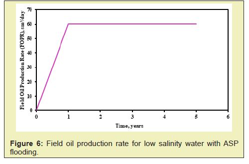
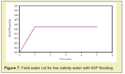
The Figures 5-7 show the oil recovery, oil production rate and water cut profile, respectively for low salinity water flooding and ASP flooding from the start of production up until five years. The synergized effect of the injected chemicals (alkaline, surfactant and polymer) and low salinity water flooding yielded an oil recovery of 93% at the end of the production period Figure 5. Interfacial tension reduction by the surfactants, increase in mobility ratio by the polymer, and the wettability change by the low salinity flooding all mobilized the oil, hence reducing the residual oil saturation. The oil production maintained a constant rate at 60sm3/day from the onset of production to the end.
of oil recovery for all flooding processThe overall oil recovery at the end of the production life for each flooding process discussed was compared on the same graph to illustrate their oil recovery proficiency. Low salinity combined with ASP flooding yielded the best result, and conversely, conventional (high salinity) water flooding yielded the least oil recovery efficiency. The graph is illustrated in Figure 8.
By the reservoir's energy only, production amounted to 98.3% of the oil initially in place. The normal 7-spot pattern gave the highest recovery factor (93.0%), followed by the inverse 7-spot pattern (91.0%). Direct line drive had a recovery factor of 80.0%, making it the least-performing pattern. The recovery factors of the patterns are shown in Figure 9, from the highest to the least. All secondary recovery factors fell between 68.5% and 75.0%.
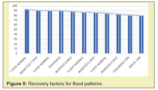
The patterns evaluated had different recoveries as a result of multiple reasons. The most likely reasons are discussed below. Normal and inverted patterns from the results shown in Figure 9, it can be noticed that the normal flood patterns performed better than their inverted counterparts. This effect could be associated with inverted patterns having fewer injector wells to sweep oil effectively. Oil is then trapped in certain areas in the reservoir, reducing the expected recovery factors.
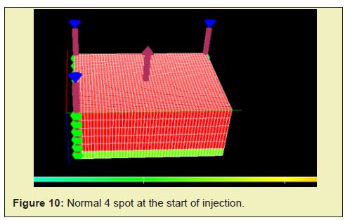
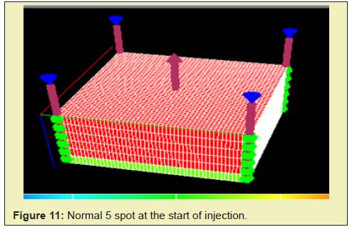
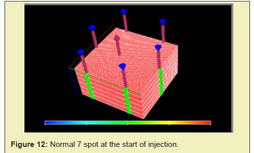
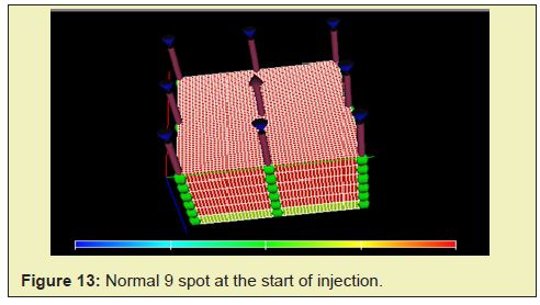
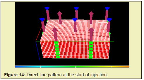
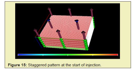
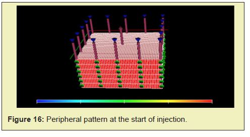
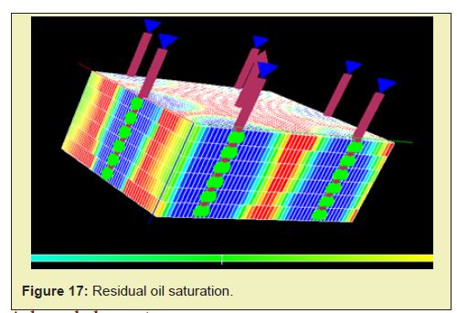
Rank of pattern recoveriesThe 3-D recovery pattern for some of the flooding techniques, particularly the normal types, the direct line, the staggered line and the peripheral are presented in Figures 10-16. The normal 7-spot pattern Figure 12 recovered the most oil, and it had just the needed number of injectors to sweep oil from all corners of the reservoir effectively. Arguably the peripheral flood pattern Figure 16 also had the means to effectively sweep oil from all directions toward the producers to prevent a trap. Logically, more injectors should lead to more recovery. However, in this case, the higher number of injectors in the peripheral pattern led to earlier water breakthroughs in the producers and higher water cuts after breakthroughs, limiting oil production. A similar situation can be observed between the peripheral flood pattern and the normal 9-spot pattern Figure 13. The peripheral pattern had a higher recovery because it lacked an in-field injector than the normal 9-spot pattern. The extra injector resulted in water breakthrough instead of oil sweep efficiency. Using more injectors at times becomes counter-productive. The residual oil saturation for the normal 7-spot pattern is depicted in Figure 17.
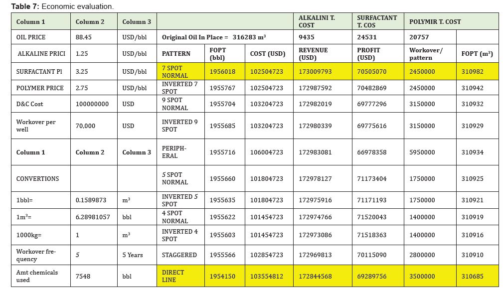
Profitability analysis of the project is a critical evaluation after the technical analysis is completed, and this analysis is the basis for the investment decision of the project. The economic evaluation featured the price of oil and each chemical used as well as their concentrations, the initial oil originally in place, estimated drilling and completion cost, duration of the project and the workover per well. These factors were used to calculate the cost, revenue and profits of the project for each pattern. The economic analysis is represented in Table 7.
Eleven different water flood patterns were successfully modelled and evaluated in this study using black oil simulation, economic analysis, the combine effect of low salinity water flooding and alkaline-surfactant- polymer flooding in a reservoir initially saturated with oil and water. The patterns showed varying recoveries while incurring some costs. From the results it can be established that:
- Low salinity water flooding with a salt concentration of 1kg/m3 recovered more oil than high salinity water flooding. Oil recovery was 30% for conventional water flooding and 55% for low salinity flooding. At the end of the production period, low salinification water flooding again produced lower water cut.
- The injection of alkaline, surfactant, and polymer in conjunction with low salinity water resulted in a 93% oil recovery. This was the highest of all the flooding processes studied. The standard 7-spot pattern yielded the highest profits when combined with ASP, while direct line drive yields low profits.
- The synergy of the Alkaline-Surfactant-Polymer flooding and per the economic analysis, has a profit margin of 40.7% which concludes its economic viability.
We would like to thank anonymous reviewers for their contribution to this research. We would also like to thank the developers of the Eclipse Software without their brilliant inventions, this project would not be possible. Finally, we thank the University of Mines and Technology, Tarkwa, Ghana, GNPC School of Petroleum Studies, Petroleum and Natural Gas Engineering Department for their immense support.
None.
None declared.
- 1. Sheng JJ. Modern Chemical Enhanced Oil Recovery: Theory and Practice, Elsevier Publishing Corporation, New York. 2011;pp.617.
- 2. Behnoudfar P, Rostami A, Hemmati Sarapardeh A. Miscible Gas Injection. In: Bahadori A. ed. Fundamentals of Enhanced Oil and Gas Recovery from Conventional and Unconventional Reservoirs, Gulf Professional Publishing. 2018;pp.101-138.
- 3. Speight JG. Heavy oil production processes. Gulf professional publishing, Texas. 2013; pp.180.
- 4. Smith JT, Cobb WM. “Waterflooding”, Midwest Office of the Petroleum Technology Transfer Council. 1997;pp.1-4.
- 5. Brantson ET, Ju B, Appau PO, et al. Development of hybrid low salinity water polymer flooding numerical reservoir simulator and smart proxy model for chemical enhanced oil recovery (CEOR). Journal of Petroleum Science and Engineering. 2020a;187:106751.
- 6. Brantson ET, Osei H, Essuman J, et al. Hybridization of low salinity water assisted foam flooding in carbonate reservoir for enhanced oil recovery, 6th UMaT Biennial International Mining and Mineral Conference, Tarkwa, Ghana. 2020b.
- 7. Seccombe J, Lager A, Jerauld Gary J, et al. Demonstration of Low-Salinity EOR at Interwell Scale, Endicott Field, Alaska”, In SPE Improved Oil Recovery Symposium. Society of Petroleum Engineers (SPE-129692-MS), Tulsa, Oklahoma, USA. 2010;pp.12.
- 8. Lager A, Webb K, Black C. Low Salinity Oil Recovery - An Experimental Investigation1. Petrophysics. 2008;49 (01).
- 9. Sun X, Zhang Y, Chen G, et al. Application of Nanoparticles in Enhanced Oil Recovery: A Critical Review of Recent Progress. Energies. 2017;10(3):1-6.
- 10. Gbadamosi AO, Junin R, Manan MA, et al, An Overview of Chemical Enhanced Oil Recovery: Recent Advances and Prospects. InternationalNanoLetters.2019;9:171-202.
- 11. Abhijit S, Achinta B, Keka O, et al. Comparative Studies on Enhanced Oil Recovery by Alkali-Surfactant and Polymer Flooding. Journal of Petroleum Exploration and Production Technology. 2012;2(67):2-3.
- 12. Opoku AP, Pu H, Marfo SA, et al. Surfactants usage in enhanced oil recovery operations coupling harsh reservoir conditions: an experimental review. Arabian Journal of Geosciences. 2022;15(5):1-31.
- 13. Hawez H. Eclipse Chemical Enhanced Oil Recovery. 2013.
- 14. Brantson ET, Ju B, Wu D, et al. Stochastic porous media modeling and high-resolution schemes for numerical simulation of subsurface immiscible fluid flow transport. Acta Geophysica. 2018;66(3):243-266.
- 15. Zhang Y, Xie X, Morrow NR. Waterflood Performance by Injection of Brine with Different Salinity for Reservoir Cores”, SPE Annual Technical Conference and Exhibition, 11-14 November, Anaheim, California, USA. 2009;pp.1-12.
- 16. Pogaku R, Mohd Fuat NH, Sakar S, et al. Polymer Flooding and Its Combinations with Other Chemical Injection Methods in Enhanced Oil Recovery. Polymer Bulletin. 2017;74:1-22.
- 17. Dang CTQ, Nghiem LX, Chen Z, et al. Modelling Low Salinity Waterflooding: Ion Exchange, Geochemistry and Wettability Alteration. Society of Petroleum Engineers Annual Technical Conference and Exhibition, New Orleans, Louisiana, USA. 2013;pp.22.
- 18. Teklu TW, Alameri W, Graves RM, et al. Low Salinity Water-alternating-CO2 EOR. Journal of Petroleum Science and Engineering. 2016;142(32):101-108.
- 19. Supaprom C, Wannakomol A. A Comparision Study of Five-Spot and Nine-Spot Water Injector Patterns to Enhance Oil Recovery of Maesoon Oil Field by Computer Simulation (Doctoral dissertation, Master Thesis, Suranaree University of Technology, Thailand). 2012.
- 20. Broni Bediako E, Brantson TE, Asante AT. Numerical Simulation of the Combined Effects of Low Salinity Water and Alkaline-Surfactant-Polymer Flooding. International Journal of Oil, Gas and Coal Engineering. 2021;9(4):46-58.
- 21. Abadli F. Simulation Study of Enhanced Oil Recovery by ASP (Alkaline, Surfactant and Polymer) Flooding for Norne Field C-Segment. Unpublished MSc Thesis, Norwegian University of Science and Technology. 2012;2(63):3-4.
- 22. Tarek A. Reservoir Engineering Handbook, Gulf Professional Publishing, Burlington, USA. 2010;pp.1454.
- 23. Oksol B. The Million Dollar Way (The Bakken Blog). 2014.
- 24. Mahani H, Sorop TG, Ligthelm D, et al. Analysis of Field Responses to Low-Salinity Waterflooding in Secondary and Tertiary Mode in Syria, In: SPE Europec/EAGE Annual Conference and Exhibition, Vienna, Austria. 2011.
- 25. Erke SI, Volokitin YE, Edelman IY, et al. Low Salinity Flooding Trial at West Salym Field. Society of Petroleum Engineers Improved Oil Recovery Conference, Tulsa, Oklahoma, USA. 2016:pp.11.

