Lost-circulation is one of the major challenges in fractured formations limiting the optimized fast drilling, which is prone to huge economic and environmental losses. The leakage pressure prediction has been a major concern in the industry. To solve this problem, a method for the construction of leakage pressure body in fractured formations is proposed in this paper. First, a leakage pressure prediction model for different fracture scales is optimized. Secondly, a fitted relationship between leakage pressure differential and leakage rate is developed based on the leakage data of the actual drilled wells, which is used to correct the leakage pressure in the priority formation. Finally, a three-dimensional (3D) body of regional stratigraphic leakage pressure is established based on kriging interpolation. This paper presents an example analysis of a fractured formation in the Halfaya oil field. The result shows that the modified formation leakage pressure profile matches the field drilling conditions. The 3D visualization of the regional leakage pressure provides a more intuitive understanding of the distribution of leak-prone formations in the area, which can provide a targeted decision basis for leakage prevention and plugging in the area.
Keywords: Fractured formation, Leakage pressure, Kriging interpolation, 3D pressure body, Leakage correction
Lost-circulation is one of the common downhole complications during the drilling process.1,2 It is a working condition that drilling fluid leaks into the formation during the drilling process.3,4 Lost-circulation is mainly subject to the following factors:
-
1. There is a positive pressure difference in the formation, and the pressure of the fluid column in the wellbore is greater than the pressure of the fluid in the rock.
2. The presence of various leakage channels in the formation and a large enough space to contain the liquid.
3. The opening size of the leakage channel should be larger than the particle size of the drilling fluid or working fluid solid phase in the wellbore.
Data pre-processing
Currently, pressure prediction using logging data is one of the widely used methods,12 but due to external and human factors, it tends to produce large random influence values on the measurement results. This makes the pressure profiles predicted from the logging curves have statistical undulations and burr disturbances. Therefore, the logging data are first preprocessed to remove the noise using the unconfirmed rational number method by follow formulas.
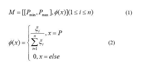
Where φ(x) denotes the confidence distribution function of pressure values; n denotes the number of pressure points in the selected formation; Pi denotes the pressure value corresponding to a certain depth within the selected formation; ξi denotes the number of Pj (j≠i) within the neighborhood | Pj-Pi | ≤ λ of Pi; λ denotes the magnitude of the change in pressure value within a certain thickness.
By using the above method, the logging data can be pre-processed to eliminate burr interference while preserving the original trend of the log curve, based on which a more reasonable and credible pressure can be obtained.
Leakage pressure calculationLeakage can be classified by the cause of the leak into the following categories: induced leakage, fracture leakage and differential pressure leakage.13 Induced leakage is caused by the fluid column pressure in the well. The channels in the formation that were not enough to cause well leakage are connected to each other and extend deeper into the formation, forming a larger channel and causing well leakage.11 Fracture leakage is caused by the formation being fractured because the fluid column pressure in the well exceeds the maximum pressure-bearing capacity of the weak formation downhole, resulting in the formation of new leakage channels.14 Differential pressure leakage is caused by the natural pore or fracture in the formation while drilling, this kind of leakage will not change the connectivity of the leakage channel under the limited pressure.15 In this paper, for conventional microfracture-induced and fracture leakage pressure calculations, based on logging data, the minimum horizontal ground stress is considered as the formation leakage pressure, and the equation is as follow:

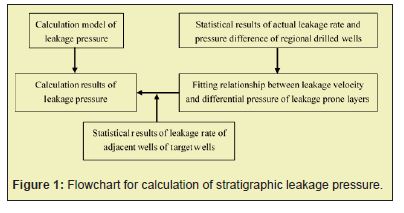
Natural hole pressure-differential leakage has a larger leakage channel size, resulting in less resistance to fluid flow in the channel, which allows drilling fluid to enter the formation more easily, resulting in a larger drilling fluid leakage situation.1 Therefore, for the calculation of natural pore differential leakage pressure, a combination of conventional calculation model and a correction method of fitting relationship between leakage rate and leakage pressure difference in regional leakage prone layer is used for the calculation of formation leakage pressure. The leakage pressure difference is the difference between the drilling fluid column pressure and the pore pressure in the well, and the leakage pressure difference has a good correlation with the leakage rate. From the field leakage data, the leakage rate is fitted to the leakage pressure difference, and the leakage pressure can be recognized as the drilling fluid column pressure when the leakage occurs, so that the leakage pressure can be corrected Figure 1.
Based on the well deployment and geological stratification information obtained from the logging data of completed wells in the region, the same formation was vertically sliced according to the stratigraphic trend (N equal longitudinal splits were made for each well location). The horizontal is based on geodetic coordinates, and the vertical is the number of layers in the slice. Wells in the same layer are considered to be at the same relative depth in that layer. The higher the density of slices, the more computationally intensive it is, but the accuracy increases. The elements of the matrix represent the formation pressure information of each well in the region:

Spatial interpolation method is a numerical method, which treats known point information as a function of space, and uses the position relationship between unknown points and known points to find the unknown point information.16,17 Spatial interpolation is able to convert point information into surface information in the lateral direction and a small amount of drilled well information into area information in the spatial direction. In this paper, the ordinary kriging interpolation method is used,18,19 and the specific steps are as follows:
Finding the plane variation function in different layer cellsFor simplicity of expression, let pk(G) be the regionalized random variable of formation leakage pressur, (X,Y) denotes the plane coordinates, x, y represent the geodetic coordinates respectively, and k represents the number of layers. Let d denotes the separation distance on the center plane of the grid where the two well points are located. pk(G) and pk(Gi+d) are the formation pressure values of the regionalized variable pk(G) at locations Gi and Gi+d, respectively. N (d) represents the total number of pairs of grids separated by a distance d in the center plane of the grid where the two well points are located, and according to the definition of the variance function, the formula for calculating the variance function is:

According to step (1) and the formation leakage pressure calculation resluts of neighboring wells, a series of variation function values γk(d) can be calculated for each grid layer at different separation distances d.
The variance function theoretical model chosen is the spherical model.

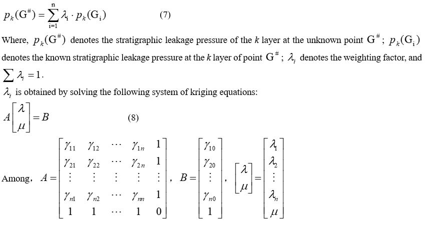
Prediction of formation leakage pressure at unknown well locations
According to the kriging method, the formula for calculating formation pressure at unknown well location is
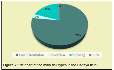
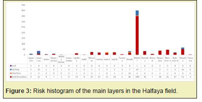
There are complex geological conditions in the Halfaya oil field in Iraq, which is characterized with the coexistence of a composite salt layer in the upper and middle parts, a high-pressure brine layer and a low-pressure leaky layer, and a variable pressure system. In addition, the reservoir giant thick carbonate rocks are developed in combination with sandstone and shale, and the distribution of pores and local fractures is irregular. From the well history statistics of more than 200 wells collected in the Halfaya area, it appears that more than half of the wells have experienced downhole complications, 137/213 wells have experienced various degrees of leakage during drilling, and the loss of drilling time due to drilling leakage accounts for 9% of the total NPT. This indicates that well leakage is the main problem in this region. From the stratification statistics of each formation, the well leakage mainly occurred in the Mishrif, Nahr Umr and Shuaiba formations. Among them, the Mishrif and Nahr Umr formations belong to pressure differential leakage, and the Shuaiba formation is fracture leakage Figures 2,3.
Eleven drilled wells in the Hafaya block are selected as samples for the study. Based on the available logging data, the leakage pressure is calculated for these eleven wells according to the calculation method in Section 2.1. The calculation method is specified below using well H1 as an example Figure 4.
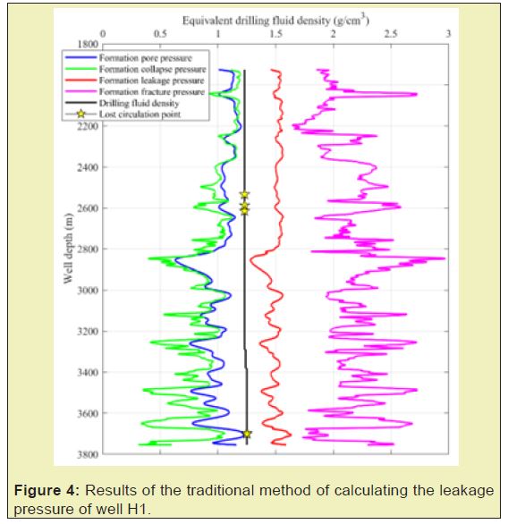
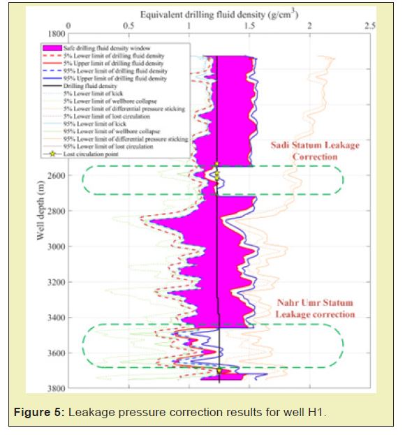
As is shown in Figure 4, the results of the conventional leakage pressure calculation method are large relative to the differential pressure leakage due to natural fracture faults, and cannot be used for accurate leakage pressure prediction. So, it is necessary to correct the leakage pressure for the key layers. And since natural fracture-based leakage in the Halfaya area is influenced by geographic location, the variability of leakage between wells in different areas is large, which will cause large errors if they are counted together, so for different layers, the relationship between leakage rate and leakage pressure difference can be fitted by sub-region for leak-prone layers. Through the statistical analysis of the leakage pressure difference and leakage velocity of the main leakage levels in the block, the probability distribution of leakage velocity and the fitting relationship between leakage pressure difference and leakage velocity for each main leakage level were obtained, so that the safe drilling fluid density window could be corrected. The corrected results are shown in Figure 5, and it can be seen that the corrected results are consistent with the actual leakage situation.
The three-dimensional bodies of leakage pressure for each formation in the Hafaya area are established according to the method described in this paper, and the results are as follows:
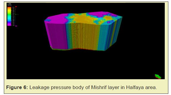
Taking the Mishrif formation as an example, we can see from Figure 6 that the trend of leakage pressure distribution is highest in the northwest and southeast and lower in the middle part. According to the well history of drilled wells in the Halfaya area, the leakage in the Mishrif formation is more serious in the northwestern and southeastern part of the wells drilled, and there is a complex fractured leakage layer, which is consistent with the actual situation Figure 7,8.
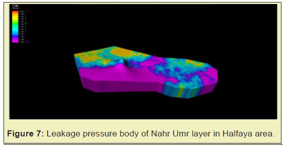
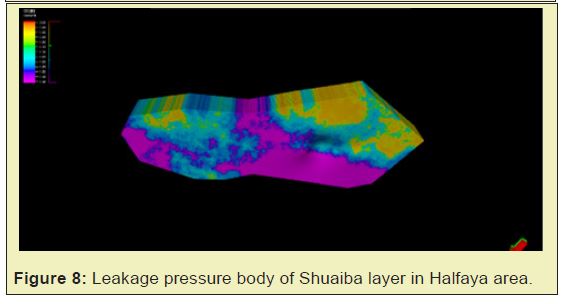
- Let stratigraphic formations be the basic studied units, using basic information from drilled wells in this area, the leakage pressure of each single well is first calculated based on the logging data of drilled wells. Then the leakage pressure is corrected according to the leakage type, and finally the leakage pressure is expanded outward according to the kriging interpolation method. The regionalized leakage pressure prediction is realized and the error is within 5%.
- The 3D visualization of regional leakage pressure can provide a more intuitive understanding of the distribution of leakage pressure in the area, which provides a better technical support for preventing lost circulation and using effective plugging materials to achieve safe drilling.
None.
None.
Author declares that there is no conflict of interest.
- 1. Mirabbasi SM, Ameri MJ, Alsaba M, et al. The evolution of lost circulation prevention and mitigation based on wellbore strengthening theory: A review on experimental issues. Journal of Petroleum Science and Engineering. 2022;211:110149.
- 2. Pu L, Xu P, Xu M, et al. Lost circulation materials for deep and ultra-deep wells: A review. Journal of Petroleum Science and Engineering. 2022;214:110404.
- 3. Daqi L, Yili K, Xiushan L, et al. Progress in drilling fluid loss dynamics model for fractured formations. Petroleum Drilling Techniques. 1900;41:42–47.
- 4. Daqi L, Yili K, Xiushan L, et al. The lost circulation pressure of carbonate formations on the basis of leakage mechanisms. Acta Petrolei Sinica. 2011;32:900.
- 5. Cai W, Deng J, Feng Y, et al. Developing a geomechanics-modeling based method for lost circulation risk assessment: A case study in Bohai Bay, China. Journal of Petroleum Science and Engineering. 2022;210:110045.
- 6. Liu Z, Ma Q, Shi X, et al. A dynamic quantitative risk assessment method for drilling well control by integrating multi types of risk factors. Process Safety and Environmental Protection. 2022;167:162–172.
- 7. Han C, Guan Z, Xu C, et al. Study on Method of Determining the Safe Operation Window of Drilling Fluid Density with Credibility in Deep Igneous Rock Strata. Mathematical Problems in Engineering. 2021.
- 8. Deng J, Liu Y, Yu B, et al. Formation fracture pressure prediction method in high temperature and high pressure formations. Petroleum Drilling Techniques. 2009;37:43–46.
- 9. Yan J, Mian C. Prediction of borehole stability by seismic records. Acta Petrolei Sinica. 2004;25:89.
- 10. Yin Z, Huang S. Fracture Determination by Means of 3-Dimensional Seismic Data. Petroleum Exploration and Development. 1999;26:78–80.
- 11. Zhai X, Chen H, Lou Y, et al. Prediction and control model of shale induced fracture leakage pressure. Journal of Petroleum Science and Engineering. 2021;198:108186.
- 12. Afsari M, Amani M, Razmgir S, et al. Using drilling and logging data for developing 1d mechanical earth model for a mature oil field to predict and mitigate wellbore stability challenges. International Oil and Gas Conference and Exhibition in China. 2010.
- 13. Lavrov A. Lost circulation: mechanisms and solutions. Gulf professional publishing. 2016.
- 14. Guan Z, Chen T, Liao H. Theory and technology of drilling engineering. Springer. 2021.
- 15. Yang J, Sun J, Bai Y, et al. Status and Prospect of Drilling Fluid Loss and Lost Circulation Control Technology in Fractured Formation. Gels. 2022;8:260.
- 16. Otchere DA, Hodgetts D, Ganat TAO, et al. Static reservoir modeling comparing inverse distance weighting to kriging interpolation algorithm in volumetric estimation. Case study: gullfaks field. Offshore Technology Conference. 2021.
- 17. Shi C, Wang Y. Non-parametric machine learning methods for interpolation of spatially varying non-stationary and non-Gaussian geotechnical properties. Geoscience Frontiers. 2021;12(1):339–350.
- 18. Meng J. Raster data projection transformation based-on Kriging interpolation approximate grid algorithm. Alexandria Engineering Journal. 2021;60(2):2013–2019.
- 19. Pesquer L, Cortés A, Pons X. Parallel ordinary kriging interpolation incorporating automatic variogram fitting. Computers & geosciences. 2011;37:464–473.

