A better understanding of hydraulic fracturing behavior is even more crucial in unconventional plays as more new-well or infill-well are drilled and completed nowadays. Having integrated different sources of information/data such as the general trend of hydraulic fracturing practices during the last 20 years, DFIT and fracturing simulation, core analysis data, outcrops, the Hydraulic Fracturing Test Site (HFTS), and fracturing monitoring in the wells or between wells such as pressure, tracers, DAS, DTS, DSS and so on, we proposed an innovated conceptual model of hydraulic fracturing coming along with some associated concepts; The transdisciplinary integration approach we used in this research follows all fundamental physics law and meticulously logical reasoning and analogy with crossing validation, the first principle thinking epistemologically because of the physics of unconventional fracturing is much more complicated than any single discipline can explain. More often than not, the solution coming from any discipline or data source is not a unique one. The cognition of the morphology or the called fracture pattern of hydraulic fracturing is critical, which is virtually the conceptual model of fracturing. The conceptual model can directly impact the fracturing design and the way to evaluate actual fracturing.
Using the proposed conceptual model, Fracturing Impact Volume (FIV), one can better explain what fracturing has done for unconventional plays and why it worked. With the proposed conceptual model and tossing aside the fracture network as the fracturing goal, many current fracturing practices can be improved significantly, and the way of production can be revised. This is a significant concept shifting in the unconventional fracturing arena, and it is certainly not an easy task, but this paper makes a compelling case. With the FIV model in mind, the perception of “the greater the pumping rate, the better the fracturing be” becomes unnecessary or makes little sense. This paper will decode the shale oil/gas flow mechanisms and demonstrate a better way to fracture and produce unconventional resources like shale oil/gas.
Keywords:Conceptual model, Unconventional reservoir, Fracturing, Transdisciplinary integration
It has been about 20 years since the shale gas revolution started in the US at the Barnett shale. All kinds of data and information on fracturing and shale oil/gas production or ultra-tight sandstone, the unconventional oil/gas, have been overwhelming recently, but that was not the case 15 years ago. A question is what we have learned from the last 20 years of fracturing, and the answer may be that we learned a lot or massive, and the difference may be between infancy then and puberty now. Now a fascinating question comes; Has the fundamental conceptual model of fracturing changed? If it is a yes, change to what; if not, why when you have thousand times more data available than before? This paper will discuss the existing fracture network conceptual model and the one tomorrow and its impact on the fracturing industry, from research to operations in the fields.
In the unconventional reservoirs, we tap right into the source rock. Production from unconventional reservoirs is a function of reservoir matrix porosity, permeability, hydrocarbon saturation, pore pressure, contact area, and conductivity provided by hydraulic fracturing and effectively enhanced oil recovery techniques. Comparing frac design from 2005 to today, reducing clustering spacing and increasing proppant job sizes have brought massive change and value to many companies across various basins.1 This trend has been well recognized as a part of the best practice trend of fracturing for shale oil/gas during the last almost 20 years. This is the reality as Figure 1 indicates that all kinds of data are pointed to the fundamental conceptual model changes. In the early 2000s, large-scale fracture networks (FN), or discrete fracture networks (DFN), which presumed the large-scale nature of fractures intersected with fracturing fractures as in Figures 1 A,B,C,2,3 the concept was prevalent in the academy and industry. About ten years ago, between 2012-2014, the modern fracturing of shale started to kick off, which includes multi-stage and multi-cluster horizontal well fracturing with tighter cluster spacing.
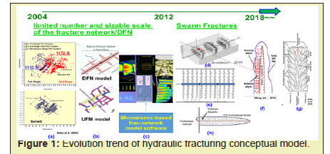
After 2014, some people began to question the DFN model or called it DFN and microseismic-based SRV.4 With more production data and fracturing -related data from Hydraulic Fracture Test Site 2(FHST-2) didn’t support the DFN conceptual model. Some new conceptual models were proposed, as in Figures 1,d,c, and e, similar to the swarm model.
Figure 2 indicates the trend of shale fracturing techniques evolution from the early 2000s to the middle 2010s, where fracture spacing gets much tighter and more completed plug & perf in the well completion.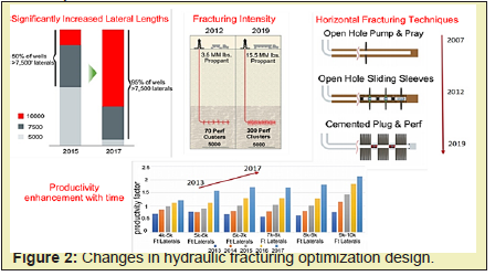
Now, we must understand what this change means for us to design better fracturing jobs. This paper will explain this in detail.
Where does the fracture-network/DFN model come from
It is fair to say that the fracture network concept in multistage hydraulic fracturing of a horizontal well was evoked from microseismic mapping interpretation at Barnett shale. In a paper by Fisher,2 microseismic event clouds, which were widespread over 1000 to 1500ft per stage in a horizontal well fracturing, were interpreted as fracture-network, the outline area as stimulated fairway area Figure 1,a. The allegorical interpretation for forming a fracture network was the natural fractures intersecting with fracturing fractures.
Furthermore, the area covered by the widespread clouds, the fairway area times fracture height or the thickness of pay named as stimulated reservoir volume (SRV) later on.5 “The key words “stimulated” and “volume,” when those two words come together, create the power, like a magnet to metals, attracting too many people in the fracturing arena. Many people think intuitively that the microseismic-based SRV, better called MRV (microseismic reservoir volume), is a truly stimulated reservoir volume, and someone even further interprets SRV as a crushed reservoir volume three-dimensionally, which means the fracture network not only develops vertically but also develops horizontally following the layers of the formation. Why could this possibly happen by so much misunderstanding for the SRV?”; Wang pointed this out in 2016.6
The microseismic-based model DFN, with a limited number and sizable scale of the natural fractures, intersected with hydraulic fractures and formed the DFN. This is where the model came to the horizon then. Some commercial fracturing software entered the market a while later and implemented this conceptual model in the codes, so-called hydraulic fracture network modeling with very uniform fracture network grids. The fracturing software has explicitly characterized the scale of DFN, and evidentially the scale of natural fractures should be in dozens of meters range to form the fracture networks through intersecting with fracked fractures, which is in dozens of meters spacing in the early 2000s then.
For whatever reason, many people adopted this micro seismic-based DFN concept, and some use this concept today. “A common view on production mechanisms in shales is that “because the formations are so tight, gas can be produced only when extensive networks of natural fractures exist”.7 Some companies still use forming the fracture network or not as a criterion of successful fracturing.
However, there is growing evidence that any existing natural fractures may be filled with calcite or other minerals. It has even been suggested that open natural fractures would be detrimental to Barnett shale gas production.8 Our studies show that natural fractures are not the opposite of creating a larger fracture surface area. Commercial exploitation of low-mobility oil/gas reservoirs has been improved with multi-stage hydraulic fracturing of long horizontal wells. Favorable results have been associated with large fracture surface area, not the forming fracture network or not.
Many investigators have presumed that open natural fractures are critical to gas production from deeper plays.9 Up to date, some people still believe in that concept. Whenever and whatever data may be, someone will try to make the connection to the natural fractures and fracture network. That is one of the indicators that this DFN conceptual model needs to be urgently explained and clarified in a bit detail.
Undoubtedly, it is high time and very important to clarify this fundamental conceptual model-DFN scientifically and practically, whether solid data-based or just a shaky and misleading concept. It is about the research directions and the best practices or not in the fracturing field.
Does anyone have reliable data to back up this conceptual model beyond microseismic? The outcrop someone proposed as evidence for this conceptual model is invalid. The image log does not support it much, either. This paper will elaborate on why microseismic, outcrops, and image logs cannot be used as reliable evidence for the limited number and sizable scale of the fracture network regularly or irregularly does not matter, fracture-network/ DFN.
On the other hand, plenty of data indicates otherwise against the DFN model in the shale plays fracturing. Pre-existing natural fractures do not appear necessary to achieve a complex, distributed fracture system, and fractures do not need to be forming a network/DFN or are very complex to have good production. Relative closer Planner fractures spacing with plenty of induced microfracture during fracturing can be very productive wells.
Defects of the DFN model
There are obvious defects in using the DFN fracture network model and concept, especially so many unknown parameters in the model, such as the size, total number, distribution of natural fractures, conductivity, and connectivity. This conceptual model led to some software in the market or in-house using the DFN concepts. Anyone who uses those codes has to struggle with the input data setup of the natural fractures-related parameters and input a limited number of sizable natural fractures with no idea of where and how to get data. The random input virtually makes the simulation results very questionable. But, the first thing goes to the first; the foundation and background are very doubtful for this conceptual model to be valid.
This paper will elaborate on why microseismic, outcrop, and image logs cannot be used as evidence for fracture networks. People adopt the concept that a limited number of natural fractures with large spatial distribution intersect with hydraulic fractures and form regular or irregular-shaped fractures, the DFN discrete fracture network conceptual model. Now, we have to discuss some of the foundations of the DFN concept as follows:
Some people use rock outcrops to define the natural fracture geometry of the reservoir; This can overcome the blindness and randomness of natural fracture distribution and highlight the misunderstanding of the basic principles of logical analogy geology. First, the outcrop can be used to observe many geological properties of rocks, but it cannot be used to compare the fractures in a few thousand meters deep plays. The outcrop is the product of orogenic movement in geological history, which is not comparable with source rocks, shale buried several kilometers subsurface. Secondly, the confining pressure of the outcrop is almost zero, and the confining pressure of the deeply buried shale is not only three-dimensional but also huge, which is not comparable with the confining pressure of outcrops; Thirdly, as shown in Figure 3, the outcrops of Eagle Ford and Green River, evidently there is no sizeable (a few dozen of meters) natural fracture in the outcrops. If a significant number of sizable natural fractures exist, the appearance of those outcrops will look different. Any geologist can get the same conclusion by looking at those outcrops.
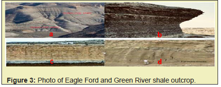
Looking at Eagle Ford and Green River’s shale outcrop, we can see that the relatively uniform layering formation stretches long and unbroken laterally. Those outcrops indicate that natural fractures in dozens of meters of scale simple not exist. How can someone imagine that the deeply buried shale with oil and gas in it will develop a lot of discrete fractures in multi-meter long? The outcrops conflict with DFN's view that discrete fracture network systems are often tens or hundreds of meters long. Even though the outcrops have significant large-scale fractures, we still can compare the outcrops to the oil and gas bearing shale subsurface with thousands meters deep for apparent reasons, as we discussed above.
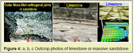
But Figure 3 shows the fracture network generated by the outcrop of limestone or massive sandstone in the early years. Still, this fracture network model concept is not related to unconventional shale. Those are sandstone or limestones. There are no comparisons, even though some software uses sandstone or limestone outcrops for shale formation—rock type matters.
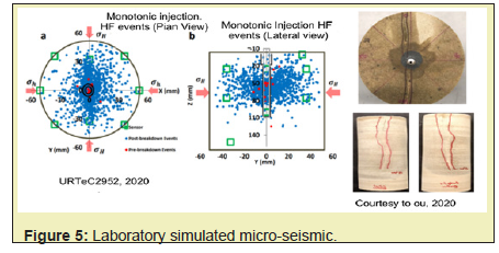
As we discussed, someone interpreted the spread out of microseismic event clouds as a fracture network, assuming that many sizable nature fractures in tens of meters intersected with hydraulic fractures. However, as shown in Figure 4, only one fracturing fracture was created during the core fracturing experiment in the laboratory, but the microseismic events were all over the core sample. Based on the microseismic-based DFN or SRV logic, one has to interpret it as the core sample having been crushed totally. It is wrong. Now it is fair to say that the microseismic data cannot sufficiently reflect the actual fracture development morphology. The accumulated error and resolution in microseismic data processing and interpretation can create very spread-out seismic cloud events that have nothing to do with the fracture network. The data of lab simulated micro seismicity is inconsistent with the fracture-network/DFN concept. And using microseismic events to be interpreted as fracture networks is not beyond doubt Figure 5.
Someone may use image logs fracture network may be another misperception because the small scale in image logs cannot be compared with a few- dozen meters of nature fractures as in the DFN model. They are not at the same level of scale. The image logs data has nothing to do with large-scale fracture networks.
What you may do when the model is used
It is not uncommon to use the discrete fracture network (DFN) model for unconventional oil and gas fracturing and production mode designs. With the fracture network model in mind, one will design a fracturing job tending to have a higher pump rate and large scale of total fracturing fluid so that a higher net pressure could be created in the fracturing jobs, and in the hope that complex fractures can be made. This logical chain is as microseismic event clouds→natural fractures and fracture networks or complex fractures→ with higher pump rate to have higher net pressure in fracturing jobs. Some operators set up the technical goal of forming a fracture network as a criterion to evaluate the success or not of a fracturing job. Putting this logical chain into practical work can be costly financially and environmentally.
This paper proposes an innovative conceptual model that can overcome and avoid the limitations and misleading existing DFN models and can better explain all kinds of data from different sources consistently, not paradoxically.
What and why FIV model
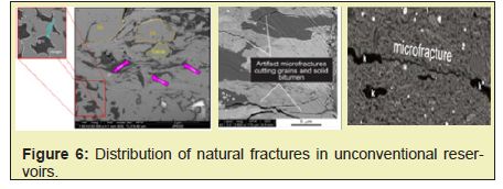
The microfractures and micropores consist of shale reservoirs, in which oil and gas are stored, not the sizable natural fractures. However, the fracture network model can neither describe nor be suitable for the microscale structures in the rock because the fracture network concept model assumes that natural fractures exist on a large scale with limited numbers. Given the particularity of this shale formation, it is necessary to consider two kinds of media in the reservoir: (1) large hydraulic fractures or identifiable fractures at the field scale (feet/meters, etc.), which function as a channel to the wells from the matrix of shale; (2) Numerous micro-fractures, organic/inorganic pores, clay mineral dehydration micro-fractures / pores and matrix, together as a reservoir system with local non-uniform permeability which is very much enhanced by the process of the fracturing, also called enhanced permeability zone (EPZ).10 This pressurized EPZ is the crucial part of the whole shale oil/gas game besides the main fractures. This is key to why fracturing worked on shale. This paper will not decode the shale oil/gas flow mechanisms in detail.
This enhanced permeability zone is mainly caused by fracturing, then put forward a new conceptual model Fracturing Influenced Volume (FIV), which can be distinguished from stimulation volume, which refers to the rock volume fractured or crushed in someone’s mind.
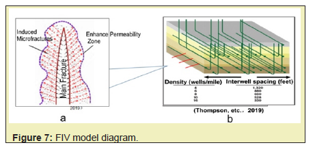
The FIV fracturing impact volume model refers to the EPZ plus the main fracture system. It should be just a fraction of the pressure difference of the reservoir in the microfractures. Micropores of unconventional reservoirs rise sharply due to the slick water fracturing, resulting in the pressure diffusion from the primary fracture to both sides and forming the pressurization effect in the area along the fracked primary fractures; The place where the pore pressure rises along the fracture due to fracturing is defined as fracturing impact volume (FIV), as shown in Figure 6, 7.
What is the FIV model Specifically
We can understand the fracturing impact volume—FIV model as follows:
Its schematic representation in Figure 7, a, indicates the primary fracture and a fracturing impacted area along the primary fracture, which includes induced microfractures, pressurized pores, and original microfractures. It has an outline along the primary fracture;
Its theoretical contents may include; in unconventional reservoir stimulation, before the rock breaks, the average pressure is Pt, which is the pressure of the area of reservoir system fluid loss increase rapidly. The initial reservoir pressure is Pi, ΔP is the additional pressure increase, as in the equation![]() . Right after and during the rock breakdown, the fluid pressure in the fracture is
. Right after and during the rock breakdown, the fluid pressure in the fracture is![]() .
.![]()
![]() , where initial reservoir pore pressure is
, where initial reservoir pore pressure is ![]() . The fluid pressure difference
. The fluid pressure difference ![]() is the driving force for induced microfractures and pore space reservoir pressurization, which create the enhance the permeability along the main fractures. These are the mechanisms of successful slickwater fracturing in shale and ultra-tight sandstone.
is the driving force for induced microfractures and pore space reservoir pressurization, which create the enhance the permeability along the main fractures. These are the mechanisms of successful slickwater fracturing in shale and ultra-tight sandstone.
Its associated or extended concepts; to generate the induced microfracture and enhance permeability zones, some level of rock brittleness is necessary, and the brittleness is a very localized property of the rock and does not bother it with fracture propagation or fracability of primary fracture; It does not require higher pumping rate.
Its validation against facts includes tight cluster or fracture spacing, laboratory experiments on EPZ and very dense fractures from the data of HFTS, and swarm fractures. The rest part of this paper will demonstrate the validation.
FIV model fully considers the pressure dependence of the permeability and leak off of the reservoir system and considers both the major fracture and the reservoir volume along the main fracture with the increasing pore pressure, called EPZ, where induced microfractures formed. The EPZ may include fracturing -induced shear microfractures, barely opened tensile micro fractures and pressurized porous spaces. Due to the existence of FIV, additional energy and reservoir permeability increment are obtained in subsequent production, and the original physical properties and energy of the reservoir are improved from the micro and macro perspectives; It is equivalent to increasing the reservoir pore pressure and initial production pressure difference, which is another mechanism for increasing production of unconventional reservoirs.
Lab studies indicated plenty of microporous space and naturally existing microfractures in shale, as shown in Figure 6.11 And fracturing induced more microfractures. Injected fracturing fluid (slickwater) powerfully penetrates the formation to create hydraulic fractures as Figure 7 shows the areas enveloped by solid red lines as a schematic diagram; As the pressure in the fracture increases, the differential pressure between fracture and reservoir increases until induced fractures along the main fracture, that is, the fracturing impacts the area or volume when the thickness or frac height is considered; The volume of this envelope is the fracturing impact volume FIV. The microfracture pressurization area is related to the microfracture density. The denser the microfracture is, the larger the microfracture pressurization area (fracturing pressure impact area) is, and vice versa.
It is worth noting that before the breakdown pressure, the injected fluid all leaks into the formation during the fracturing process.
The fracturing impact volume FIV mentioned in this section mainly refers to the process in which the micro-cracks and micropores of the reservoir system on both sides of the fracture are pressurized and diffused before and during the fracture of the reservoir system. This process is similar to the laboratory experiments called frac-n-flow done at the University of Texas at Permian Basin.
Shale oil/gas Flow mechanisms with FIV model
It is known in the shale fracturing arena that slick water played a crucial role in shale fracturing. Supposedly, pore spaces in shale are poorly connected until fracturing takes place to generate many microfractures and pressurize porous space so that enhanced perm zones are achieved. Since the osmosis diffusion and capillarity dominated the imbibition process in the ultra-tight rocks, the FIV concept is better to use to explain the oil/gas production from nano-darcy rock, matrix of rock, not the sizable natural fractures.
If the microfractures and pores in unconventional reservoirs are not better connected after fracturing, and only a limited number of large-scale fractures as channels to transport oil/gas into the well as in the network/DFN model assumed, it is hard to explain the massive production of shale oil and gas production. Overall, the flowback ratio of fracturing fluid in unconventional reservoirs is very low, which is a basic fact. Based on the DFN model, fracturing creates large-scale fracture networks within one stage and crossing stages for repeating stimulation. The mechanisms of fluid flow in shale is basically no different than in conventional. Someone explained that because of the formation's ultralow permeability, reducing the flow distance between the matrix to fracture is the main concern. Someone also suggested using a dual-media model for shale oil flow simulation for flow simulation. This model is a pure conventional reservoir concept. It didn’t touch the critical items of this fracturing game.
It is pretty easy to explain the flow mechanisms with FIV Model. One does not need to imagine having a large-scale fracture network as in DFN. Fracturing creates fractures that can be simple planner fractures with close spacing, and alone a large-scale fracture, an enhanced perm zone (EPZ)is also being developed. That is the beauty part of the FIV model. The widely distributed microfractures and micropores in unconventional reservoirs are pushed and activated by penetration of frac fluid during fracturing, forming EPZ, which makes the oil and gas in original microspores/microfractures more mobile because a large amount of highly penetrating fracturing fluid (slickwater) has entered or leaked off to the microscope level of the matrix along the main fractures.
Therefore, the FIV model is the reasonable interpretation of the successful mechanisms of shale oil/ gas fracturing; that is, the initiation of the primary fracture dominates the flow model, and the overall fracturing flow system under the matrix system (also the matrix system of the combination of the fracturing influence volume FIV and the primary fracture) including some natural fractures of a specific scale (whether or not they exist).
What you will do based on the FIV model for shale oil/gas
It is unnecessary to conduct a fracturing job with a higher pumping rate and a more significant amount of fracturing fluid under the new conceptual model, FIV, which is just opposite to the one with the DFN model. With calculated optimal pumping rate and amount of frac fluid, multi-cluster creates multi-fracture in each stage of a horizontal well. Significant fracture surface area can be generated, and EPZ with induced microfracture helps activated oil/gas flow to fractures and the fracked well.
In addition, there are differences in fracturing design and parameter optimization of fracturing implementation, such as well spacing and fracture spacing between DFN and FIV models. In short, the FIV model fundamentally changes the guiding principle of unconventional fracturing and puts forward different requirements for the fracturing optimization design and production mode.
Obviously, in terms of the fracture geometry in shale fracturing, including ultra-tight sandstone, there are two types of conceptual models; one is the DFN as discussed above, other is the non-network/non-DFN model, including FIV and swarm as proposed in this paper. The FIV and swarm are very similar; both are about a fracture system along the main fracture associated with a fracture system, a vast number of induced microfractures, and enhanced permeability zones or a bushel of minor parallel fractures.
Whatever conceptual model one proposes, supporting evidence, data and arguments are needed. There are two types of supporting evidence.
The first one is rigorous logical thinking and reasoning; The second one is: supporting data and information. The microseismic-based DFN model cannot pass the first type of supporting evidence because it did not follow rigorous logical thinking and reasoning. The micro-seismic data can’t support that conceptual model because the resolution problems, accumulated computation errors, and interpretation errors were not appropriately addressed when this concept was proposed, as mentioned above. Most outcrops are against the fracture network /DFN model, as discussed above. When one frac stage was in1000 ft to 1500 ft, and microseismic clouds covered over 1500 ft, the large fairway was considered to be stimulated, then about ten years later, about 1/10 length per stage was widely used. What kind of rigorous logical thinking and reasoning is this? This is an excellent example that the trend of the best practices of fracturing during the last 20 years is strong evidence not to be ignored—the laboratory simulated micro-seismicity against the DFN.
On the other hand, the rationality of the FIV model can be verified in many ways; The trend of the best practices of fracturing supports it; The outcrops indicate it is correct; The laboratory data support it.
Now the field monitoring data, including tracer experiment, field Diagnostic Fracture Injection Test (DFIT), inter-well and internal well monitoring data, hydraulic fracturing test site (HFTS), chemical data of the flowback water, and some laboratory core analysis data will be presented below.
Well Monitoring Data DTS, DAS, DSS
There is monitoring well B4H and a fracturing well B3H on the site, as shown in Figure 8. The DAS data of the fracturing well are collected for analysis and inversion. The strain can be calculated by the acoustic wave (a type of micro-seismic) measured by the continuous optical fiber in the well; the geometry of the fracture is inversed. Fractures in well B4H stage1 and stage 26 were used to monitor fracturing-driven interaction (FDI) in well B3H, as shown in Figure 8. The wells are 720 feet apart horizontally and 210 feet apart vertically.

In Figure 9, the warm color in the DAS monitoring diagram indicates that the fracturing fluid enters the perforation cluster. For the Extreme Limited Entry (ELE) case, after dropping the well-head pressure (WHP) by 1300psi, as shown in Figure 9,a. Lower WHP drop occurred in ALE, likely linked to less perforation erosion. This aid in continued slurry flows to all clusters, which delivered higher cluster efficiency than ELE, as shown in Figure 9,b.12 In B3H, as the fracturing operation goes on, it may be caused by perforating erosion. As time goes on, fewer pe the fracturing fluid. The overall DAS indicated that one key point is that each cluster or fracture in those fractured stages grows independently rather than growing in a network. This is essential information for anyone who will design a fracturing well.
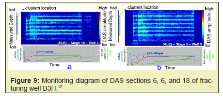
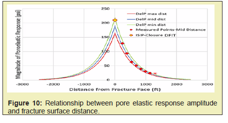
Figure 10 shows the relationship between the magnitude of the pore elastic response and the distance from the fracture surface; the red diamonds represent the measured poroelastic response at the middle points from the fracture surface of those seven stages, and the yellow diamond represents the net pressure from DFIT. This is a case study, and the study shows that “planar fracture geometries created during the hydraulic stimulation”.13 If we interpret it in terms of the DFN model, the poroelastic response amplitude of the pore should not be a sharp point. Still, it should have a much higher value of the direct pressure response through fracture connection rather than poroelastic response, and the sharp curve shall be much flat rather than in sharp decline. The trend of the pore-pressure changes in Figure 10 indicates that the fracturing impact zone can be about 1000 ft away from the fracture surface. This pore pressure change trend away from the fracture surface can be observed in almost every well, but the pressure value should differ. One of the advantages of using this method is that it is based on linear poroelasticity, a simple physical model. This is a part of the fracturing process, creating induced microfractures and the EPZ along the main fracture. This is another data validation of the FIV model.
Tracer experimental data (proving the rationality of the FIV model)
Figure 11 shows the trend of salinity over time. We believe that the fractures with smaller aperture sizes become more critical as the flowback process progresses. Therefore, the high-salinity water produced later is mainly produced from secondary fractures. Salinity response is dominated by mixing with hyper-saline formation water.
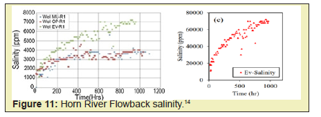
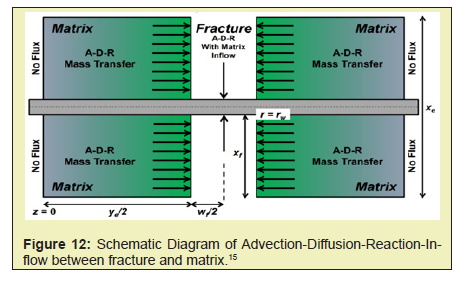
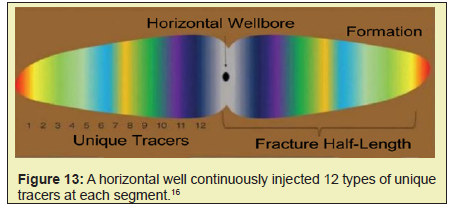
Figure 12 shows a schematic diagram of advection-diffusion-reaction-inflow between fracture and matrix. Chemical tracers can give us a lot of information about fracturing. As an example, a tracer experiment was conducted in a horizontal well drilled and completed in the Wolf camp B formation of the Delaware Basin, shown in Figure 13. At the heal-most stage, 12 types of unique tracers were injected continuously at each segment. A mixture of all tracers was detected in each sample, including the earliest flowback sample. Tracer pumped during the linear gel fluid segments at higher sand concentration flowed back faster than the slick water segments.
Conclusions can be drawn from field cases: Normally, the injected fluid should be in last-in-first-out order. But all 12 types of tracers were highly mixed and can be found at the initial flow backstage, which shows the earlier tracers also stayed at the near wellbore region. Why? This means something. This means that fracturing causes the pore pressure of the reservoir to increase, and the fracturing fluid enters the reservoir “Matrix system,” which contains micro-fractures (or capillaries), under a significant pressure difference, causing the change of discrete microstructure and forming the fracture pressure impact zone (FIV) in the near well area.
Core test data (proving the rationality of the FIV model)
The University of Texas at Permian Basin has conducted frac & flow experiments and verified the enhanced permeability zone, which supports the FIV fracturing conceptual model.14-18
Figures 14 and 15 show laboratory data supporting this view. Figures 14 shows the relationship between effective fluid pressure difference and surface water absorption at different confining pressures; However, the surface water absorption increases with the increase of the effective fluid pressure difference, and the surface water absorption is greatly affected by the effective fluid pressure difference. Figures 15 is the red curve in the left figure is derived separately to approximate the relationship between the dimensionless fluid pressure difference and the dimensionless permeability; It can be concluded that with the increase of fluid pressure difference, the connectivity between micro-fractures improves, and the effective permeability increases.
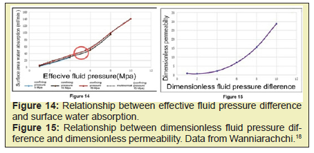
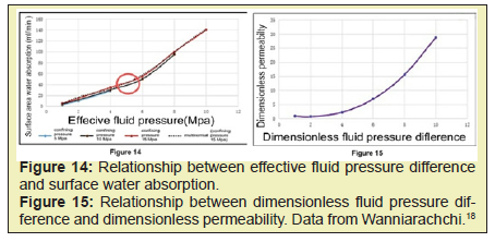
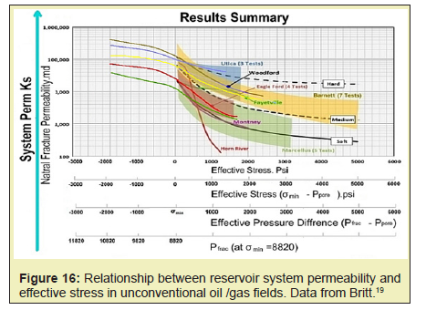
Figure 16 shows the relationship between the effective stress and the permeability of the reservoir system in several unconventional oil/gas fields. The permeability of the reservoir system increases with the decrease of effective stress, mainly due to the improvement of the connectivity of micro-fractures with the reduction of effective stress. The data used in Figure 16 was the reversed calculations from the paper19 with some extension calculations. The effective pressure is the difference between the pressure in the fracture and the pore pressure in the reservoir, which increases when the pressure in the fracture increases due to fracturing. The effective pressure reaches zero when the pore pressure is equal to the breakdown pressure, where it is at the fracture tips. At the left part of the x-axis at 0 at effective stress or pressure, that region indicates the fracture forms. On the right side of the x-axis at 0 at effective stress, it indicates that the pore pressure increases, the pores of rock matrix get dilated when fracture fluid the slickwater enters to the pores and creates induced microfractures as well. This is one of the key mechanisms of the success of shale fracturing.
Field Diagnostic Fracture Injection Test (DFIT) Data
The proposed FIV model (dominant diffusion model of microfracture and micropore pressurization) has been verified by the field DFIT test. The following figure shows the pressure fitting curve of the DFIT diagnostic test for gas wells in Argentina. The permeability of the DFIT diagnostic test is one order of magnitude greater than that obtained by the core test. The black line in Figure 17 indicates the original monitoring pressure, the red line indicates pressure curves fitted with core permeability and low pore pressure, and the green line indicates pressure curves fitted with DFIT permeability and low pore pressure, the blue line represents pressure curves fitted with DFIT permeability and DFIT pore pressure Figure 17.20
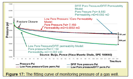
It can be seen that the blue line is the best fitting, and the green line is the worst. The blue line fits better than the red line. Because the pore pressure of the blue line uses a higher DFIT pressure and the permeability uses a larger DFIT permeability; It shows that with the increase of pore pressure, the effective stress decreases, the connectivity between micro fractures and micropores improves, and the effective permeability increases. During the initiation and extension of the primary fracture, the microfractures and micropores in the reservoir are energized due to slickwater penetrated into; the connectivity of the microfractures in the reservoir becomes better; with the leak-off increases, the permeability increases, and the whole percolation characteristics in the near-well area are enhanced. This also shows one of the meanings of the fracturing impact volume FIV model.
A Summary and Comments on Hydraulic Fracturing Test Site (HFTS)
Based on the published data and information, the HFTSs support the FIV and are against the DFN model. There are over a dozen of papers on the HFTS’s topics. Two typical papers are fascinating, and would like to discuss them here.
One paper was presented by U of Texas at Austin at 2021 URTeC, entitled “Statistical Analysis of Fractures from the Hydraulic Fracture Test Site 1”. They analyzed over 600 ft of the cores, and they found that 309 natural fractures were observed, and only 26 were reactivated by hydraulic fracturing; they concluded as “Creating a new hydraulic fracture is 14 times more likely than reactivating a natural fracture, and fewer than 1 in 10 natural fractures were reactivated during hydraulic fracturing”.21 They further concluded as “We have also seen the minimal effect that the hydraulic fracturing process has on the natural fracture system in place. With this in mind, perhaps natural fractures should not be expected to add as much porosity and surface area to the fracture network as traditionally thought.22
The Lawrence Livermore National Laboratory presented another one at SPE conference in 2020, then SPE Journal in 2021. This research has also shown that the main fracture and many closely spaced swarming fractures are in an essentially parallel fashion.
“In field-scale simulations and the efficacy of this approach to enable realistic predictions of reservoir responses to fracture swarms, without the need to model tightly spaced fractures individually”.23 A swarm frac model can be simulated similarly to the main fracture associated with a fracture system, which consumes more energy than the main fracture alone.
After reviewing and analyzing some key aspects of shale oil/gas hydraulic fracturing during the last about 20 years, including the trend of best practices of fracturing, core sample laboratory testing, DFIT, HFTS information, on-site fracturing well-monitoring data, and other related information, using a transdisciplinary approach, we proposed a new fracturing conceptual model, fracturing impacted volume (FIV) as presented in this paper.
This paper has demonstrated that the feature of the microscale fracture network along the main fracture dominates the shale fracturing process and reflected the unique features of shale fracturing and its flow mechanisms after hydraulic fracturing. Any fault and large-scale natural fracture may complicate the fracturing process, but the paper has demonstrated that is not a dominant factor and not a positive factor neither in the unconventional fracturing arena.
On the other hand, by tracing the origin or derivation of the DFN conceptual model, this paper makes a strong argument regarding the validation of the DFN model. As the paper presented, a list of counter-argument was demonstrated. And beyond that, as a big-data expert indicated in a hydraulic fracturing conference during the keynote speech, “scale is a big problem in oil/gas reservoir computation area.” Yes, indeed. The large-scale fracture network and DFN concepts argument have no reliable data support especially when the scale is considered from the concept to the computation model. Still, micro or small scales, like centimeter, millimeter, or smaller fracture networks are most likely in the fracturing process, but that has nothing to do with the DFN which is in large scale or mesoscale at least from the numerical modeling point of view.
Why do we need to take the time to discuss the DFN model if the model does not impact the frac job design, implementation, and research? Unfortunately, it does a lot. Some operators are still using whether to form a fracture network or not as the criteria to judge fracturing as successful or not and insisting on pursuing higher pumping rates and a larger amount of total frac fluid, in the hope to create higher net pressure as goals in the fracturing job. The DFN or fracture network-based concept led to a philosophy of the fracturing practice that the higher the net pressures, and more complex fractures to be created, and better fracturing results. Actually, this is an underlying logic of DFN for many people. But this may not be a good perception nor a good fracturing practice either.
Given the way of fracturing and well performance improvement, the fracturing impact volume (FIV) model is quite different from the DFN model on fracturing practice beyond the mechanisms and theory of fracturing. FIV model focuses more on the pursuit of optimal production and EUR by utilizing an optimized pumping rate and a moderate amount of the frac fluid and keeping them well-balanced with the cluster and well spacing in a fracturing job. With the FIV model in mind, the perception of “the greater the pumping rate, the better the fracturing be” has no room, or makes not much sense. This paper will not decode the shale oil/gas flow mechanisms.
The proposed fracturing conceptual model will invoke some changes on how we think the unconventional fracturing and led to a better understanding the unconventional fracturing theoretically and practically.
The author would like to appreciate Dr. M. Smith and Mr. D. Stemberger for their meaningful discussion and suggestions; would like to thank W. Zhang, Y. Chen and B. Wang of IUT and its associated Huaxia Rising Energy staff to help with the figures and some editing works. And would like to appreciate those who have been mentioned in the reference and those who may be missed from the reference. They made this paper possible.
None.
None declared.
- 1. Belyadi H, Fathi E, Belyadi F. Hydraulic Fracturing in Unconventional Reservoirs: Theories, Operations, and Economic Analysis. 2nd edn. 2019.
- 2. Fisher M, Heinze J, Harris CD, et al. Optimizing Horizontal Completion Techniques in the Barnett Shale Using Microseismic Fracture Mapping. SPE Annual Technical Conference and Exhibition, Houston, Texas; 2004.
- 3. Wu R, Kresse O, Weng X, et al. Modeling of Interaction of Hydraulic Fractures in Complex Fracture Networks. Paper presented at the SPE Hydraulic Fracturing Technology Conference, The Woodlands, Texas, USA. SPE-152052-MS; 2012.
- 4. Cipolla C, Wallace J. Stimulated Reservoir Volume: A Misapplied Concept? SPE Hydraulic Fracturing Technology Conference, The Woodlands, Texas, USA, SPE-168596-MS; 2014.
- 5. Mayerhofer MJ, Lolon EP, Warpinski NR, et al. What is Stimulated Reservoir Volume (SRV)? Paper SPE 119890 presented at the SPE Shale Gas Production Conference, Fort Worth, Texas, USA; 2008.
- 6. Wang Y, Wang ZP. Years of Tight Oil Fracturing: What Have We Learned? Society of Petroleum Engineers, SPE181810 MS; 2016.
- 7. Carlson ES, Mercer JC. Devonian Shale Gas production: mechanisms and Simple Models. J Pet Technol. 1991;43(04):476–482.
- 8. Bowker K. HAPL Technical Workshop. 2008.
- 9. Walton I, McLennan J. The Role of Natural Fractures in Shale Gas Production. the International Conference for Effective and Sustainable Hydraulic Fracturing (HF2013), Australia; 2013.
- 10. Ghosh DS, Zhou D, App J, et al., Insights into Fracture Fluid Distribution and Fracture Geometry in Hydraulically Fractured Horizontal Wells through Thermal Simulations and Fiber Optics Distributed Temperature Sensing (FO-DTS) Measurements. URTEC3028; 2020.
- 11. Loucks R, Reed RM. Natural Microfractures in Unconventional Shale-Oil and Shale-Gas Systems: Real Hypothetical, or Wrongly Defined. GCAGS Journal. 2016;5:64–72.
- 12. Vissotski A, Singh A, Rijken P, et al. Analysis of Completion Design Impact on Cluster Efficiency and Pressure-Based Well Communication in HFTS-2 Delaware Basin. Unconventional Resources Technology Conference (URTeC); 2021.
- 13. Haustveit K, Elliott B, Roberts J. Empirical Meet Analytical-Novel Case Study Quantify Fracture Stress Shadowing and Net Pressure Using Bottom Hole Pressure and Optical Fiber. Society of Petroleum Engineers. 2022.
- 14. Zolfaghari A, Dehghanpour H, Ghanbari E, et al. Fracture Characterization Using Flowback Salt-Concentration Transient. SPE J. 2016;21(01):233–244.
- 15. Kovacs W. Flowback Water Chemistry Forecasting Flowback Water Recovery and Its Salinity Response to Adequately Prepare for Water Recycle and Reuse. Canadian Business Conferences Canadian Shale Water Recycling and Reuse Congress. 2015.
- 16. Tian W, Darnley A, Mohle T, et al. Understanding Frac Fluid Distribution of an Individual Frac Stage from Chemical Tracer Flowback Data. Paper presented at the SPE Hydraulic Fracturing Technology Conference and Exhibition, The Woodlands, Texas, USA. 2019.
- 17. Zeng Z. Frac-n-Flow Testing to Screen Brittle Fracture Stages in Wolfcamp Formation, Permian Basin, USA. MDPI, Basel, Switzerland. 2012.
- 18. Wanniarachchi M Ayal, Ranjith PG, Perera Mandadige, et al. Investigation of Depth and Injection Pressure Effects on Breakdown Pressure and Fracture Permeability of Shale Reservoirs: An Experimental Study. Applied Sciences. 2017.
- 19. Britt LK, Smith MB, Klein HH. Production Benefits from Complexity – Effects of Rock Fabric, Managed Drawdown, and Propped Fracture Conductivity. Society of Petroleum Engineers. 2016.
- 20. Buijs H, Ponce J. An Engineered Approach to Hydraulically Fracture the Vaca Muerta Shale. Society of Petroleum Engineers. 2018.
- 21. Male F, Rysak B, Dommisse R. Statistical Analysis of Fractures from the Hydraulic Fracture Test Site 1. Unconventional Resources Technology Conference (URTeC). 2021.
- 22. Curtis JB. Fractured shale-gas systems. AAPG Bulletin. 2002;86:1921–1938.
- 23. Fu W, Morris PJ, Fu PC, et al. Developing Upscaling Approach for Swarming Hydraulic Fractures Observed at Hydraulic Fracturing Test Site through Multiscale Simulations. SPE J. 2021;26(05):2670–2684.

