This paper seeks to model and simulate a 3D Floating Production Storage and Offloading (FPSO) unit and subsea structures for the separation of reservoir fluids. In this paper, each component on the hull of the FPSO and the subsea structures were constructively designed with Python codes written in Blender software according to ship building practice and offshore standards. Material (colour) was added to each component as well as environmental features to depict reality for deepwater operations with extreme weather conditions. Nanofiltration (NF) membrane separation technology was implemented into the modelling process for the purification of water to reduce the sulphate content for reinjection to boost productivity. Also, this study minimizes flow assurance problems to improve subsea production system (SPS) by installing a subsea separator which allows oil, gas, water and sand slurry phases to be separated prior to being boosted up the risers. Additionally, the separator design has an integrated sand slurry handling system which ensures proper sand management. Results from this paper show a final rendered work of a new generation of FPSO design tie back from subsea structures and the simulation (subsea and surface) of the reservoir fluids separation processes.
Separation processes, Nanofiltration membrane, Hull and topsides design, Subsea production system, Flow assurance
The oil and gas industry makes use of different machinery and platform to infer the numerous capacities expected to run the industry from the ground up. The research of findings distinguishing of oil in the oil fields, underlying pilot plants to recognize the capability of the fields, drilling and extraction of the oil and gas from the fields, further processing of oil and gas into different raw products, refining products into usable end products and their subsequent storage and transportation all need different engineering vessels and machinery.1 Some of such vessels and machinery are the offshore production platforms.
These include Fixed Platform, Tension Leg Platform, Complaint Tower, Sea Star Platform, Spar Platform and Floating Production Storage and Offloading vessels.2 Moreover, Terpstra3stated that the introduction of new FPSO designs combined with topsides weighed in excess of 25,000 tonnes present new challenges to operators and designers. This has called for more consistent design guidance for these new generation of FPSOs.
In recent times, FPSOs and subsea structures have shown a fast evolution due to the emerging advanced and powerful technologies available.4,5 Parallel to these new developments coupled with industrial needs, FPSO and Subsea 3D models are being widely considered by all oil and gas industries for successful oilfield development. The design of these systems mainly includes allocation of the subsea facilities, determining the position of the FPSO’s core components and identifying the flow line routes.6 Having a plan (model) in place before you start a project is an important part of ensuring the eventual success of that project.7
The model provides a method to link related issues of interest to the layout design, yielding a practical subsea layout that can be used to confidently estimate costs and assist in decision-making for flow assurance.8 The model will also help engineers to have an idea of multiple ‘what-if’ scenarios’ during the design process which enables them to know potential issues in advance. A 3D model gives you a simple and efficient method of looking for these issues and also help to solve facility related difficulties by analysing parts of the facility in question. Moreover, the creation of virtual models enables industries to appreciate facilities designed and participate in project evaluation and field development.
However, one of the challenges for most oil and gas field projects lies in the inability to reproduce and establish a more consistent 3D design guidance to obtain an accurate fore-idea of how FPSO and subsea systems are to be installed and arranged. In order to curb this issue, designing 3D models of FPSO and subsea system will help to generate accurate representations of the systems. Moreover, a 3D model of your facility supports this capability by providing an easy source of accurate information about the facility.7 It also allows for the evaluation of the potentials of 3D model design of FPSO and subsea system to fuel a successful oil and gas project.9 Ogbonnaya, study recommended that newly built FPSOs are more advantageous than the conversion of tankers and Very Large Crude Carriers (VLCC) which motivated the current research on improving FPSO designs for harsh environments.20
AThe rest of the paper is structured into the following sections. Section 2 describes the structural overview of the FPSO vessel. Section 3 dwells on the method used to design the FPSO vessel in Blender software. Section 4 states the results obtained from the design as well as discussion of the results. Section 5 summarizes the major conclusions obtained from the study.
Various types of production facilities are used worldwide and depending on the situation, the facilities may be fixed to the ocean floor. The use of FPSO is a well-established development concept deployed in numerous areas of the world. FPSOs are either newly built hulls or converted from existing trading tankers with new topside facilities added to the main deck.3 Tankers convention into FPSOs are more prominent than newly built facilities due to their reduced procurement schedule, reduced cost and the large selection of vessel available.10 Double sided hull configurations (usually newly built FPSOs) are normally used where conditions demand a purpose-built vessel, generally with increased or specialised storage capacity and as a floater.
The FPSO unit produces and processes crude oil and gas on the topside, and stores the stabilised oil in cargo tanks of the hull. The FPSO unit also off-loads the stabilised oil and gas to a shuttle tanker piped to a Single Point Mooring system (SPM) for the oil export. However, the FPSO alone cannot produce oil and gas in the oilfield. It entails many offshore production systems, such as the Umbilical Flow lines and Risers (UFR), Subsea Production Systems (SPS), mooring lines, a shuttle tanker, an off-loading buoy.5
Stability is one of the initial stages for any design of floating devices. This is directly associated with the general layout of the FPSO and the hull configuration. Normally, items to be considered are topsides weight distribution, riser hang-off point and storage/ballast tank configuration. The overall weight of a FPSO is dependent on the steel weight, topside weight and crude dead weight. Typically, hull steel weight is 13-16% of displacement. The hull should likewise have adequate volume to accommodate crude oil storage and segregated ballast tanks to accomplish the necessary ballast draft and avoid the bottom slamming forward.10
The turret mooring system (TMS) is made up of a turret assembly that is integrated into a vessel and permanently fixed to the seabed by means of a mooring system. The turret system has a bearing system that allows the vessel to rotate around the fixed geostatic part of the turret which is attached to the mooring system. The TMS when combined with a fluid transfer system enables the connection of pipelines to the FPSO. The fluid transfer system consists of risers between the pipeline end manifold (PLEM) at the seabed and the geostatic part of the turret. In the turret, a swivel provides the fluid transfer path between the geostatic part and the free weathervane vessel that rotates around the turret. The turret system can be located externally or internally with respect to the vessel hull structure.11
Material Used
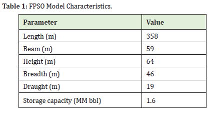
Blender is a free and open-source 3D creation suite. It supports the entirety of the 3D modelling, rigging, animation, simulation, rendering, compositing and motion tracking, even video editing and game creation (Israel, 2020). Table 1 shows the FPSO model characteristics that were employed in the design process.
Material Used
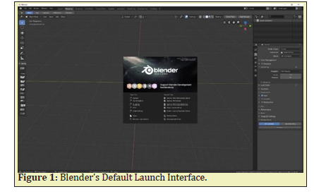
The following procedure illustrates a step-by-step approach used to obtain the 3D models from the Blender software for topsides, mooring and hull designs according to acceptable classification society’s rules and design spiral. Blender application was launched. By default, Blender shows a splash screen when the application is opened as shown in the screenshot in Figure 1.
Modelling of the Hull
The modelling procedure involved the following:
- i. At the first launch of the Blender software, a default cube, a camera and a light source display on the scene, and to start modelling the FPSO hull, the default cube is deleted by pressing X.
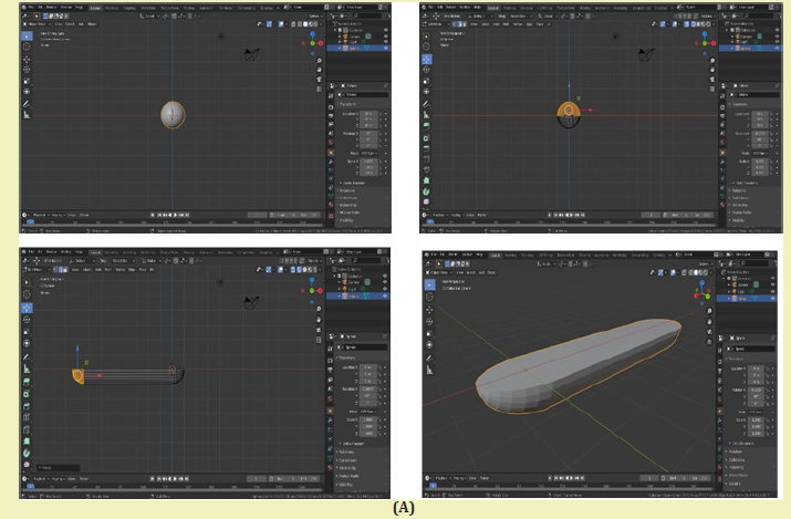
- ii. A UV sphere was added to the scene world by pressing shift + A, then the mesh was selected on the pop-up menu, with the sphere in the scene, number 3 was hit to enter into the front view of the scene world.
- iii. While the UV was selected, the R key was pressed and the number 90 was entered to rotate the sphere 90 degrees on its axis.
- iv. The tab key was pressed while the sphere was selected to enter into the edit mode, and the top half of the sphere was selected by pressing B on the keyboard. The selected top half was then deleted by pressing X.
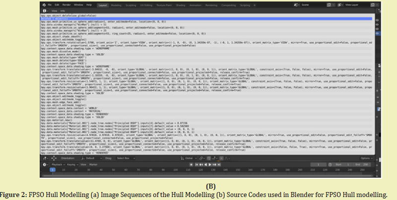
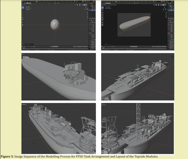
- v. Once more, half of the remaining sphere was selected and pulled on the y-axis. With the side selected, the scale was applied to it to shape it into the hull of the FPSO. To fill the top portion of the hull shaped object, the top vertices were selected, and then key F pressed to fill it. Figure 2a shows the processes in modelling the hull of the FPSO to avoid excessive environmental loading on the hull. Figure 2b shows the sample source code developed in Blender for modelling the FPSO hull.
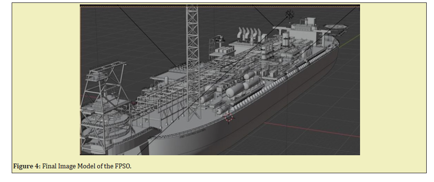
After obtaining the hull design of the FPSO, the other components like the separator, the living quarters, turret, pipeline, helipad, helicopter, plate type preheater, shell and plate heat exchanger, crane, riser, x-mas tree, subsea separator, manifold, buoyancy tank, lifeboat, hydro cyclone, cooler, dissolve gas floatation vessel, de-aeration tower, nano filtration membrane, power house and a lot more followed. All the operations performed were done in Blender’s layout and modelling workspaces. Figure 3 shows the image sequence of the workflow from Blender’s UV sphere to the point where all components were modelled. The final untextured image model of the FPSO is also shown in Figure 4.
After the modelling was completed entirely and all the necessary components of the FPSO were installed, materials (colour) were assigned to them to make them have a look comparable to what they certainly look like in reality. This was done by using the principal shader node shown in Figure 5 by switching to Blender’s shading workspace.
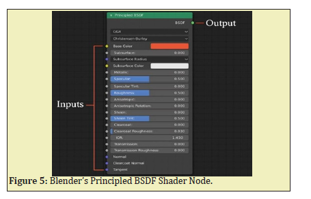
The principal shader node of Blender is used to add materials to 3D models. It also uses the node-based approach to obtain the desired look of its material. Like in other software, the preferred look of a model is obtained by combining a number of nodes in a unique way. To achieve the desired look, tens and even hundreds of these nodes are connected together to control visual properties such as depth of field, ambient occlusion, specular, glossiness, metallic, emission and a lot more.
Modelling of the Ocean
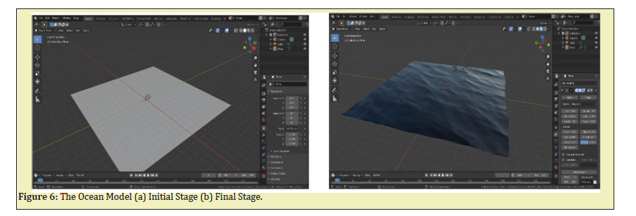
Before starting up with the ocean, the add-on for node wrangler was activated. A plane was added to the scene from the mesh option. Once the plane was on the scene, F9 key was pressed to bring up the plane settings and the size of the plane was increased to 200m. Next, you toggle into the edit mode by pressing tab key. Once into edit mode, the plane was subdivided 64 times by right clicking on the mouse. To add the ocean effect on the plane, you move to the modifier region and click on ocean to add the ocean effect to the plane. The ocean setting was implemented in the design using features such as, “Choppiness” to mimic the wavy effect of the ocean, “Scale” to design the size of the wave and “Smallest wave” gives the detail to the wave.
The resolution of the ocean was turned up to 40 to give a more realistic ocean. Next, material was added to the ocean, which gave colour and the texture to the ocean. The screen was split into two and the shader editor was activated. Again, the ocean setting was worked on. First, the roughness was put to zero to give the glass effect of water, and the base colour was set to black so that the ocean can reflect the colour of the sky. The index of refraction was set to 1.333. The final work was baked for about an hour to help with the stability of the wave motion and also to reduce the rendering time. The initial and final model of the ocean is shown in Figure 6a and b.
Texturing
Texturing is the process of assigning materials to 3D models. In most 3D software, texturing is done in a node-based approach where one shader or node is connected to another to attain the desired look. Node-based texturing is the preferred way of achieving realistic look of 3D models. The more realistic a model is expected to be, the more complex the node connections become. Texturing of models in big studios for the purpose of movies and other advanced purposes requires massive node connections. However, in events where interactivity of the models is paramount, nodes are minimized and optimized to make the interactive feature possible in real-time. Since the models for this project were geared towards the development of an interactive content, their shadings were highly optimized.
Texturing the Ocean Floor
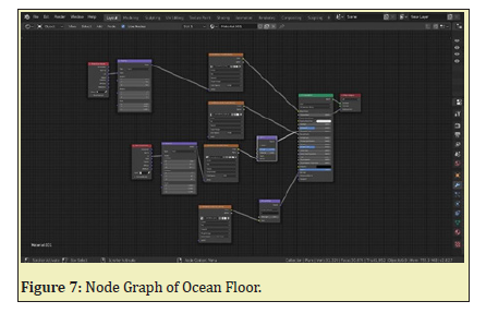
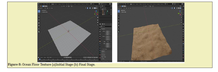
Primarily, a plane was added to the scene world, the plane was scaled up to about 300m and subdivided into 8 divisions. A principal subdivision surface and a displace modifier were added to the plane from the modifier options. With the plane mesh selected, U key was pressed to unwrap the mesh. The shader editor was activated, and an image texture node was added to the shader editor world as shown in Figure 7. A diffuse image was added to the scene by clicking on open and navigating through the images, the appropriate image was selected and added to the shader workspace. Roughness, normal and displacement texture could be added the same way as the diffuse image to give a realistic image of the ocean floor. The initial and final model of the ocean floor is shown in Figure 8.
The Array Modifier
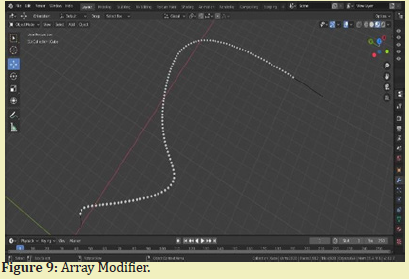
The flow of the water, oil and gas was achieved using the array modifier on a curve guide. This flow movement was achieved by adding a cube and scaling the edges to have a diamond-shape. While the diamond-shaped mesh was selected, an array modifier was applied to it. The number of diamonds can be increased to meet specification. A path curve was added to the scene world. With the path curve selected, the tab key was pressed to enter into the edit mode. The vertices of the curve were selected and manipulated to any path the diamond mesh would follow. The diamond mesh was finally parented to the curve guide as shown in Figure 9.
Upon completion of the model, a 3D modelling of the FPSO and subsea structures was developed. It also shows simulations of the oil, water and gas treatment processes. The 3D model design of the FPSO obtained provided very realistic looks of the various components of the FPSO which makes it easy to visualise and better appreciated. Additionally, the movement of oil, water and gas was accurately represented at the topside by a diamond-shape with individual colour codes of Green representing Oil, Blue representing Water and Red representing Gas. The produced products are stored on the hull before offloading to shuttle tankers through a metering pump.12
FPSO with its Component Section
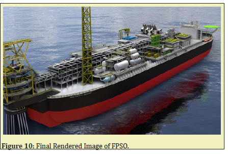
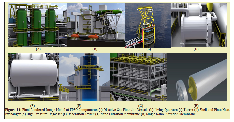
This section provides a preview of the FPSO as shown in Figure 10 (https://youtu.be/V8f_rcKwQuw ). It can be moored in 1200m of water depth indicating clearly dissolved gas floatation vessels, the living quarters, the turret, the water treatment section and various components all assembled on the FPSO as shown in Figure 11.
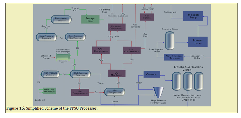
Figures 11a to 11h show the various major components designed on the topside of the FPSO structure, respectively: Dissolve Gas Flotation Vessels (Figure 11a) function by removing the remaining oil, solids and contaminate from the liquid in this vessel. Living Quarters: The living quarters (Figure 11b) provide accommodation for staff during long periods out at sea, along with control rooms, offices and recreational facilities; Turret: The turret is one of the major components of the vessel where it provides the means to which fluids are transferred from the risers to the process plant on the FPSO. Also, the turret allows weather vaning or rotation of the vessel to adjust to climatic conditions (Figure 11c). Shell and Plate Heat Exchanger (SPHE): In the SPHE (Figure 11d), the oil is heated with saturated steam until it reaches 104℃, this temperature is ideal for effective separation of the oil and water. High Pressure Degasser: The degasser (Figure 11e) is used to remove entrained gas in the fluid, and this is important for an effective phase separation; Deaeration Tower: low sulphate water is pumped into the deaeration tower which reduces the amount of oxygen in the water (Figure 11f). Nano Filtration Membrane: Filtered water is pumped into the nano filtration membrane (Figure11g) twice, through which the water is forced to reduce the sulphate content for reinjection with injection pump. A single nano filtration membrane is shown in Figure 11h. The development of a subsea separation system at the subsea level might potentially handle an increase in generated water and permit it for reinjection by using pumps to enhance reservoir pressure thereby boosting hydrocarbons productivity.13,14 Hence, the treated water is analysed before being discarded,13 and the water must contain less than 29ppm of oil by volume if it meets this specification, then the water is dumped into the ocean, if it does not, it will be sent to the produce water tank where through settling the water will be dumped into the ocean.
Subsea and Equipment Section
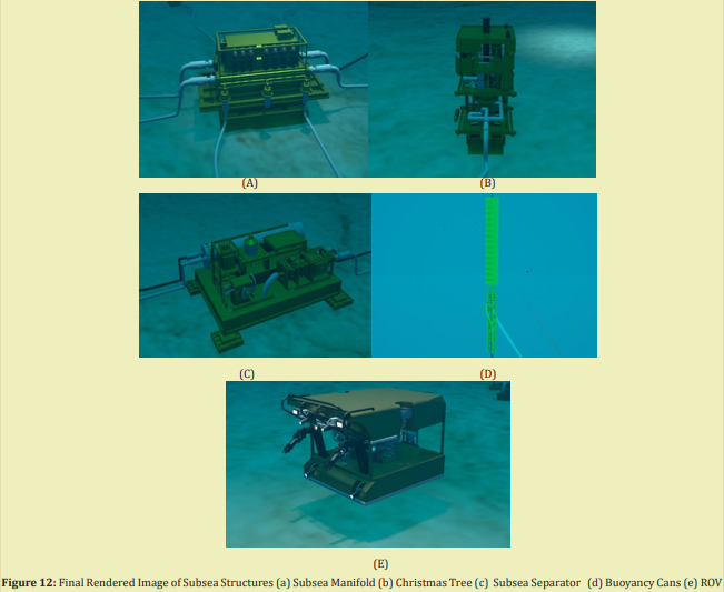
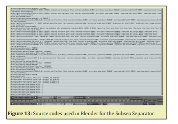
All the subsea structures were designed to meet specifications15 as shown in Figure 12 (https://youtu.be/V8f_rcKwQuw ). This section shows the subsea structures, from the risers, to the buoyancy tanks, subsea separator, manifold, remote operated vehicle, X-mas trees. Figure 12a depicts the subsea manifold (minimize the use of subsea pipelines and risers) which collects the produced fluid from several wells, regulate and optimize flow and distribute control fluids and various chemicals for the Christmas tree. Also, the Christmas tree (Figure 12b) are installed on the wellheads, and they ensure the control of the well and the transfer of hydrocarbons from the well to the manifolds. Furthermore, Figure 12c is the subsea separator that improves the field throughput, and allow gas, water, oil and sand slurry phases to be segregated prior to being boosted up the risers for flow assurance management and reduction in environmental impact.16 Also, the subsea separator has an integrated sand handling system that ensures effective and efficient disposal of sand. This improves the flow assurance by avoiding hydrates, wax, asphaltene, scale, sand, and other undesirable contents from building up in the flowlines.17 Figure 12d is the buoyancy cans with large tank-like structures built around the outer surface of the riser conductor near the top of the riser which is used to provide lift, reduce top tension and prevent excessive stresses in the riser. The final rendered image of Remote Operated Vehicle (ROV) is shown in Figure 12e with all design specifications met. Figure 13 shows the sample source code that was developed in Blender for modelling the subsea separator for flow assurance problems management.
Hydrocarbon Processing Section
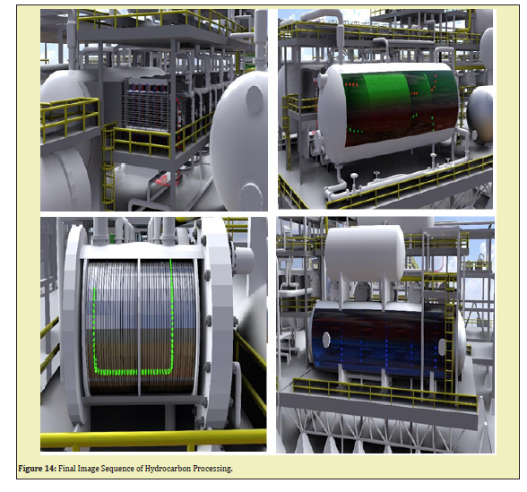
This section shows the hydrocarbon processing, with each phase moving through the treatment section, starting from the oil treatment module which includes the plate type preheater to the degasser and other crude oil treatment (https://youtu.be/V8f_rcKwQuw ). Next, it moves to the water treatment modules then finally to the gas treatment plant as shown in Figure 14. Each hydrocarbon phase is colour coded to distinguish them from one another. With red colour representing gas phase, blue representing water phase and crude oil phase represented by a green colour. Figure 15 shows the detailed schematics of the FPSO processes designed for processing the hydrocarbons.18-20
At the end of this study, the following conclusions were drawn based on the motive that a 3D FPSO and subsea structures were successfully modelled and simulated using Blender software:
- i. A detailed model of the FPSO and the subsea structures were designed according to ship building practice and offshore standards.
- ii. The model was able to show the treatment processes of the hydrocarbon phase at subsea and subsequent processing at the top side of the FPSO.
- iii. Each component on the FPSO and the subsea structures were constructively designed with Python codes in Blender beginning from the design of the hull and other components installed.
- iv. Nanofiltration (NF) membrane separation technology was implemented into the modelling process for purification of water over classical separation processes to reduce the sulphate content before reinjection to boost productivity.
- v. Also, this study minimizes flow assurance problems to improve production by installing a subsea separator which allows gas, water and oil phases to be separated prior to being boosted up by the risers. Also, an integrated sand handling system of the separator at subsea ensures proper sand management.
We would like to thank anonymous reviewers for their contributions toward this research. Finally, we thank University of Mines and Technology, Tarkwa, Ghana, GNPC School of Petroleum Studies, Petroleum and Natural Gas Engineering Department for their immense support.
None.
The authors have no disclosures or conflicts of interest.

