
The paper deals with an enhanced MATLAB Simulink model of a fuzzy-controlled system for a symmetrical six phase motor supplied with modified PD-I and PD-I fuzzy controllers and analyzes its performance and transients at special form speed references and step response. The Simulink model of the motor was developed with the actual parameters of a six-phase motor having a displacement of phase windings by 60 electrical degrees. The model of the six phase motor is based on the d-q mathematical model and indirect field-oriented control. A fuzzy controller with per unit input and output membership functions and 49 rules is designed. The simulation results are presented and analyzed. The results with modified PD-I and PI-D fuzzy controllers indicate the robustness of the modelled system with six-phase motor against disturbances and follow the reference input with great accuracy. The fuzzy controlled system’s response to complex reference input indicates a small speed delay at the beginning of the process and accurate following of the response input with an error smaller than 0.75 % during the application of load torque disturbance. The step response and response to complex reference input has no overshoot nor steady-state error.
Keywords: Six-phase motor, Field oriented control, Fuzzy controller, PI-D controller, Load disturbance, Response
Multi-phase induction motors operation is based on rotating magnetic field as in three-phase induction motors. The interest in multi-phase motors grows together with invented new power electronic converters and research in this area. The polyphase inverter divides power among inverter outputs, reducing the currents flowing through the power electronic switches, as well as phase windings. Development of multi-phase motors reduces the size and weight of the actuators. Articles1-4 give a detailed overview of the advantages of multi-phase electric drives. The multi-phase motors and drives are notable for their improved reliability: they can operate under faulty conditions after the loss of one or more converter outputs. Research of multi-phase induction machines3 states, that multiphase machine and its control electronics should be considered as a system. Simulation of complex non-linear system even using well known motor d-q models does not allow using of common simulation packages and needs built in blocks of MATLAB/Simulink environment.
Many references analyze the operation of multi-phase motors with phase faults consider that multi-phase motors can operate as long as at least three phases remain healthy.
Multi-phase motors have been applied in areas such as variable-speed applications,5 traction systems of railway vehicles,6 and energy and electrical transportation applications.7 They are also used in submarine applications,8 centrifugal pump systems,9 as well as in electrical vehicles.10,11 Electrical vehicles use various galvanic batteries or accumulators to supply electrical equipment with direct voltage. Sometimes direct current voltage is converted to alternating or brushless DC motors are used. The advantage of batteries and accumulators is their mobility, they have no alternating current components in their voltage. However, these sources also have some disadvantages. First of all, it is pollution of nature at producing and recycling of those. The energy delivered by the batteries to the device is significantly lower than the energy consumed when charging it. Despite that, the batteries are he main source of electric vehicles and together with multiphase converters providing successful electric drives.
The control methods of the multi-phase induction motors are the same as for three-phase motors.5 A lot of studies are based on the vector control12 and rotor flux-oriented control13-15 and direct torque control with.16-18
Principles of three phase converters can be applied to control of multiphase motors, assuming three-phase winding as subset, and N subsets make multiphase system19 and this system can be divided to three phase structure; then multiphase converter consisting of three phase inverters can control each three-phase winding set separately.
Fuzzy control systems are recommended to use for controlling very complex processes having no strict mathematical descriptions or a simple mathematical model; high-order nonlinear systems; where the processing of linguistically formulated expert knowledge must take place. The application of fuzzy control is not recommended for use: where the required result can be obtained using the classical theory of automatic control; if the studied system has a formalized and adequate mathematical model, if the task can be solved at all.
In this way, regardless of the existence of a mathematical models and the possibility of solving the task by classical methods, problems arise in the development of vector control systems of induction drives that are difficult to solve by classical methods. They are identified by large volumes of calculations, that need to be performed in real time; permanent errors in the system, due to imprecise measurements of observed parameters, which also causes errors in unobserved parameters.
Accumulation of errors in the operating process, requires additional compensation operations, resulting in a further increase in the number of corresponding operations. Adding to all this the ambiguous requirements of the mechanical part of the electric drive system, the appeal to fuzzy control in this case becomes not only justified, but also quite relevant.
Comparison of some classical PID and fuzzy logic controllers is made20,21 is based on the plant, described by high order transfer functions.
The six-phase motor is described by high order nonlinear differential equations; therefore, this experience could not be applied directly.
The fuzzy-logic control of the six-phase induction motors was analyzed in16,17,22.
Analysis of performance six-phase electric drive using hybrid fuzzy controllers, including modified PI-D controllers will extend knowledge base in selection of suitable controller.
The mathematical description of the six-phase motor is based on the d – q model in revolving reference frames. Two approaches in the analysis of multi-phase motors are used. The mathematical model of the multi-phase motor is assumed the same as three-phase motor in.23,24 This model is used in22 to model and analyse the six-phase induction motor with a fuzzy-logic speed controller. The five‑phase induction motor used to run the electric vehicle is considered in,10 where the assumed mathematical model and d – q equations are the same as for a three-phase induction motor.
The second approach is based on the d – q equivalent motor circuit with two stator windings supplied by two direct current voltages and a single rotor winding shared by both.
This method is widely used in the analysis of multi-phase motors, including six-phase motors8,25,26
Article26 compares tabulated step response and transient at determined input specifications for the six-phase induction drive with indirect field‑oriented control system equipped PI, PD, PID controllers and PI, PD, PI-D fuzzy controllers.
The motor d – q equations in the synchronously rotating reference frame ![]() are expressed as voltage drops
are expressed as voltage drops ![]() ,
, ![]() , as well as
, as well as ![]() and
and ![]() , across two sets of stator windings and rotor windings.
, across two sets of stator windings and rotor windings.
Simulink model of six-phase drive
The six-phase motors can have different spatial displacement between two sets of three-phase windings: 30 or 60 degrees. The motors with 60 degrees displacement are called symmetrical six-phase motors and having 30 degrees displacement are referred to as asymmetrical. The motors with no spatial displacement between two sets of three phase windings are named dual six-phase motors. Decoupling Clark’s transformation for six sinusoidal voltages gives six new equations. The equations in stationary reference frame, α−β (or ds‒qs), pair is the same as equations for a three-phase motor. This pair provides coupling between stator and rotor and producing electromagnetic torque. Assuming that the motor is supplied with sinusoidal voltages and the field is sinusoidal, the x−y voltage components are equal to zero. According to2 since the rotor winding is short circuited the zero components also will not exist.
Indirect field-oriented control
Block diagram of indirect field-oriented control of six-phase induction motor with fuzzy control and PI-D, PI-D fuzzy controllers is presented in Figure 1. Six-phase converter comprises two three phase Simulink inverter blocks separately generating three phase voltage sets ![]() ,
, ![]() ,
, ![]() and
and ![]() ,
, ![]() ,
, ![]() where phase voltage
where phase voltage ![]() lags by 60 electrical degrees voltage
lags by 60 electrical degrees voltage ![]() . Two field-oriented blocks together with PWM generators elaborate pulses for inverters, based on torque reference, obtained from fuzzy control block and currents of the motor
. Two field-oriented blocks together with PWM generators elaborate pulses for inverters, based on torque reference, obtained from fuzzy control block and currents of the motor ![]() ,
, ![]() ,
, ![]() and
and ![]() ,
, ![]() ,
, ![]() . Two sets of voltages form the set of six-phase voltages, shifted by 60 electrical degrees.
. Two sets of voltages form the set of six-phase voltages, shifted by 60 electrical degrees.
Three phase voltage sets ![]() ,
, ![]() ,
, ![]() and
and ![]() ,
, ![]() ,
, ![]() are transformed to two-phase stationary reference frame and then to two-phase rotational frame, rotating with synchronous speed. Motor model is elaborated in synchronous rotational reference frame. Motor output is torque and speed, as well as
are transformed to two-phase stationary reference frame and then to two-phase rotational frame, rotating with synchronous speed. Motor model is elaborated in synchronous rotational reference frame. Motor output is torque and speed, as well as ![]() currents in rotational reference frame. The
currents in rotational reference frame. The ![]() currents are transformed to two phase currents into stationary reference frame, afterwards each set is transformed to three phase set
currents are transformed to two phase currents into stationary reference frame, afterwards each set is transformed to three phase set ![]() ,
, ![]() ,
, ![]() and
and ![]() ,
, ![]() ,
, ![]() constituting feedback to Field oriented control blocks 1 and 2.
constituting feedback to Field oriented control blocks 1 and 2.

Model of indirect rotor flux orientation system
Two reference frames stationary ![]() and revolving at synchronous speed
and revolving at synchronous speed ![]() are shown in Figure 2.
are shown in Figure 2.

In indirect field-oriented control rotor flux vector is aligned with ![]() axis of revolving
axis of revolving ![]() reference frame.
reference frame.
![]() is angle between two reference frames.27 It changes with rotor rotation. Rotor flux
is angle between two reference frames.27 It changes with rotor rotation. Rotor flux ![]() is aligned with
is aligned with ![]() axis and its projection to
axis and its projection to ![]() axis
axis ![]()
![]() and
and![]() . Then torque, delivered by induction motor is calculated as:
. Then torque, delivered by induction motor is calculated as:
where P is number of poles and ![]() is torque producing current.
is torque producing current.
Motor synchronous speed ![]() is sum of slip speed
is sum of slip speed ![]() and electrical rotor speed
and electrical rotor speed![]() :
:
![]() (2)
(2)
and angle
![]() (3)
(3)
![]() , (4)
, (4)
where ![]() is rotor time constant.
is rotor time constant.
Closed loop implementation under constant flux condition requires to calculate reference current ![]() from reference flux
from reference flux![]() :
:
![]() (5)
(5)
Current component ![]() in revolving reference frame is proportional to reference torque
in revolving reference frame is proportional to reference torque ![]() and is calculated as:
and is calculated as:
![]() ’ (6)
’ (6)
where ![]() and
and![]() is field producing current.
is field producing current.
The angular position of flux vector is obtained on the base (1) and (5) equations:
![]() , (8)
, (8)
where![]() is measured mechanical speed of the motor.
is measured mechanical speed of the motor.
Vector control Simulink model of six-phase motor is included in Figure 1. Vector control block is elaborated on the base of equations (1–8) and together with reference frame conversion equations 28-31produces transform of reference frame. The field-oriented control model was simulated with PI controllers.
Fuzzy controller
Structure of fuzzy logic controller is shown in Figure 3.

Operation of fuzzy logic controller is based on sets. Each set represents some linguistic variables defining the possible state of the output. Each possible state of the input and the degrees of change of the state are a part of the set, depending upon which the output is predicted.
Fuzzification
The fuzzification block converts each piece of input data to degrees of membership by a lookup in one or several membership functions.32 Fuzzy knowledge database stores the knowledge about all the input-output fuzzy relationships. It also has the membership function which defines the input variables to the fuzzy rule base and the output variables to the plant under control.
Fuzzy rule base stores the knowledge about the operation of the process of domain. The proposed system controller is based on the error, and the integral of error as inputs.
The controller consists of the knowledge base and the inference engine. The knowledge base consists of the membership functions and the fuzzy rules, which are obtained by knowledge of the system operation according to the environment.
Knowledge base defines the rules represented by IF-THEN rule base, relating the input and output variables.
The inference engine, which is based upon the input fuzzy sets, uses the IF-THEN rules in the knowledge base to make the decisions. According to relationships, given
In Table 1, forty-nine IF-THEN rules are developed to design operation of the system.

Membership functions
The applied fuzzy rule contains the fuzzy variables (speed, torque) which are defined by several fuzzy sets. An elaborated fuzzy set is defined by a linguistic variables NB (negative big), NM (negative medium), NS (negative small) ZE (zero), PS (positive small), PM (positive medium), PB (positive big), which are defined by membership functions shown in Figure 4. The forty-nine IF-THEN rules relate input signals and output. Two input signals enter the Table I.

Error is the difference between speed reference and actual speed, and derived error is a cumulative error.
All membership functions for the system input and output are assumed symmetrical triangles of the same width. The leftmost and the rightmost are chosen as shouldered ramps. Error and error change membership functions are defined on already known input and error values.
Defuzzification
The output of the inference engine produces the output for the fuzzy set. The method of defuzzification used in this is the centroid or centre of gravity to calculate the final fuzzy value. In this way the final crisp value of reference for field-oriented control system torque T* is obtained.
PI-D and PI-D fuzzy controllers
The basic PID control system shown in Figure 5, where R(s) is reference signal, Y(s) is system output, or controlled value.33
PID controller transfer function is Laplace transforms ratio of control signal U(s) and error signal E(s):
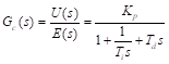 (9)
(9)
Gain Kp, time constants Ti and Td are obtained using Ziegler Nichols tuning rules. The first one method uses unit step response, the other employes critical gain and critical period.
Nevertheless, classical methods give only approximately good results. Final tuning of controller depends here on ability of researcher to make final tuning. Plant in our case is designed system with field-oriented control of six-phase motor. Due to nonlinearity of differential equations, describing the six-phase motor, the system cannot be described by any transfer function. There appears possibility to apply fuzzy logic controllers to obtain desired transient specifications of the system.


Analysis of controlled system with classical PID states, that if the reference input is a step function, then, due to the derivative term in the control action, the controlled variable u(t) will become delta function. Therefore, in designed PID controller the transfer function of real differentiating element with small time constant in the denominator is used. Then the derivative action becomes not delta function, but sharp function at unit step input. This phenomenon is called set-point kick.
PI-D controller
To avoid the set-point kick phenomenon, the derivative action is used only in the feedback path.
The differentiation is applied only on the feedback signal and not on the reference signal.
The block diagram arranged in this way is called the PI-D control and shown in Figre 6
For PI-D control closed loop transfer function is:

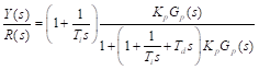 (11)
(11)
If the system has no reference signal and noises, the closed loop transfer function includes controller transfer function in denominator as in (10) and (11):
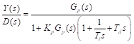 (12)
(12)
The denominators of all transfer functions are the same, i.e., the characteristic equation is the same, that indicates the same transient specifications, governed by PID controller.
Simulation results of system with PI-D controller
Simulink model of controlled system with PI-D controller with differentiating in feedback signal is shown in Figure 7

Step response
The step response of a field-oriented six-phase drive control system with a PI-D controller is shown in Figures 8-10.


Figure 8 indicates that motor starts at no load. The motor reaches its maximum starting torque of 13.8 Nm at 0.08 s. Settling time is 0.15 s, steady state value is equal to speed reference of 40 rad/s. At time instant t=0.3, the load torque of 5 Nm is applied and speed reduces by 0.2 rad/s, i.e., by 0.5 %.
The maximum reference torque, produced by PI-D controller reaches great value of 1000 Nm. The greatest motor produced torque value is13.8 Nm.
Change of motor phase current at starting is shown in Figure 10. The greatest motor current value is 3.7 A; with increasing speed it reduces up to 0.3 A and with load it increases up to 1.8 A.
Simulation results of system with PI-D controller and provided reference speed
Typical mode of speed control system operation is acceleration, steady-state, deceleration and after reverse acceleration, steady-state, and deceleration to zero speed. Figure 11 shows the speed reference and load torque as reference signals.

Motor phase current changes with speed reference and load Figure14.
The greatest current value at accelerating reaches 3.2 A, while at load it is approximately 2.5 A


Simulation results of system with fuzzy PI-D controller and provided reference speed
Hybrid PI-D fuzzy controller is given in Figure 15. It is based on PI-D model with differentiation in feedback signal.

Simulation of step response
Simulation results of motor speed and motor torque at step response are presented in Figure 16. Due to load appears shot time speed reduction by 1%. Settling time is equal 0.14 s.

Reference torque, motor torque and load are presented in Figure 17.

Error due to application of load torque at 0.3 s is equal to 0.5 %.
Simulation results of system with fuzzy PI-D controller and provided reference speed
Reference speed and motor speed are shown in Figure 18.

Due to load motor speed reduces by 0.75 %, as shown in zoomed speed view in Figure 19.

Reference torque, motor torque and load torque are given in Figure 20.

The greatest reference torque value is 22.3 Nm at time t=0.03s, the greatest developed motor torque is 11.4 Nm at 0.05 s.
On the base of simulation results the tabulated values of step response presented in 31, can be fulfilled by new results.
This study is devoted to the development problem of a complex, controlled six-phase drive model, including controlled frequency converters and indirect vector control. The model employed built-in Simulink and Simscape blocks and designed modified PD-I and hybrid PD-I fuzzy controllers.
The six-phase voltage was generated by two controlled converters, producing two sets of three-phase voltage shifted by sixty electrical degrees.
Fuzzy controllers, based on forty-nine linguistic rules with unity membership functions, were designed and implemented in the model. PD-I and PD-I fuzzy controllers were designed. Heuristic PD-I tuning methods, based on the experience gained by tuning PI, PD and PID fuzzy controllers, were used.
Both designed systems indicated good step response and performance specifications. The load reflected in decrease of speed was the same for both systems; it did not exceed 0.75 %. The PI-D and PI-D fuzzy controller removed this decrease and had no steady-state errors.
Both PI-D and PI-D fuzzy controllers step response provide good specifications at load: error due to application of load torque at 0.3 s is equal to 0.5 %.
The amplified reference torque, produced by the PI- D fuzzy controller had a realistic value of 22.3 Nm; that with the PI-D controller reached 68 Nm. Nevertheless, the motor could not produce torque, greater than 13,7 Nm in all cases. This value corresponds to the calculated breakdown torque.
A comparison of the step response in the systems with modified PI-D, and PI-D fuzzy controllers indicated that these systems have neither steady-state error nor overshoot.
Application of step response in systems with modified PI-D controllers have limitations: in real systems, a torque reference of 1000 (Nm) can hardly be achieved. These controllers should be replaced by hybrid supplied by fuzzy controllers. Alternatively, adaptive controllers should be designed and applied.
In fuzzy controller development, future work will be devoted to tuning each proportional, integral, and derivative gain for classical PID and modified PI-D and I-PD controllers in line with the model. Adaptive controllers should also be designed and the experimental base enhanced.
The complex, controlled six-phase drive model, including controlled frequency converters and indirect vector control we developed. Using built-in Simulink and Simscape blocks, we designed modified PI-D and PI-D fuzzy controllers.
The fuzzy controller, based on Mamdani membership functions and forty-nine rules, was designed and supplied with a PID controller.
The developed Simulink model of a six-phase motor drive, controlled by PI-D and PI-D fuzzy controllers or its one’s dual parts, can be adapted to control real-time systems.
Both controllers provide good transient response specifications, which could help in developing robust systems.
The step response at the hardest input‒the step reference‒was simulated.
A comparison of the step response across these systems indicated that they have neither steady-state error nor overshoot. Settling time of PI-D controller is 0.15 s and PI-D fuzzy controller is a bit shorter: it takes 0.14 s.
None.
This Research Article received no external funding.
Regarding the publication of this article, the authors declare that they have no conflict of interest.
- 1. GK Singh. Multi-phase induction machine drive research - A survey. Electric Power Systems Research. 2002; 61:139-147.
- 2. E Levi, R Bojoi, F Profumo, et al. Multiphase induction motor drives–a technology status review. IET Electr Power Appl. 2007;1:489-516.
- 3. KB Yadav, AK Mohanty, P Kumar. Recent research trend on multi-phase induction machines. Proc of Int Conf on Control Communication and Power Engineering. 2014.
- 4. F Barrero, MJ Duran. Recent advances in the design, modeling, and control of multiphase machines - Part i. IEEE Transactions on Industrial Electronics. 2016;63:449-458.
- 5. E Levi. Multiphase electric machines for variable-speed applications. IEEE Transactions on Industrial Electronics. 2008;55:1893-1909.
- 6. AV Brazhnikov, IR Belozerov. Prospects for the use of Multiphase Inverter-fed Asynchronous Drives in the Field of Traction Systems of Railway Vehicles. International Journal of Railway. 2012;5:38-47.
- 7. V Bugade. Multiphase Induction Motor Drive for Energy and Electrical Transportation Applications. Int J Res Appl Sci Eng Technol. 2018;6:166-174.
- 8. Akpama EJ. Six Phase Induction Motor Modelling for Submarine Application. 2018;13:61-66.
- 9. MI Abdelwanis , F Selim. A sensorless six-phase induction motor driving a centrifugal pump system. 2017 19th International Middle-East Power Systems Conference, MEPCON 2017 –Proceedings. 2018:pp.242-247.
- 10. Y Rao G Ravindranath. A novel electric vehicle control - electronic differential - strategy using five phase induction motor. National Conference Proceeding NTSET. 2018;032:153-159.
- 11. MA Frikha, J Croonen, K Deepak, et al. Multiphase Motors and Drive Systems for Electric Vehicle Powertrains: State of the Art Analysis and Future Trends. 2023.
- 12. R Bojoi, A Tenconi, G Griva, et al. Vector control of dual-three-phase induction-motor drives using two current sensors. IEEE Trans Ind Appl. 2006;42:1284-1292.
- 13. SN Vukosavic, M Jones, E Levi, et al. Rotor flux oriented control of a symmetrical six-phase induction machine. Electric Power Systems Research. 2005;75:142-152.
- 14. KK Mohapatra, RS Kanchan, MR Baiju, et al. Independent field-oriented control of two split-phase induction motors from a single six-phase inverter. IEEE Transactions on Industrial Electronics. 2005;52:1372-1382.
- 15. GK Singh, V Pant, YP Singh. Voltage source inverter driven multi-phase induction machine. Computers and Electrical Engineering. 2003;29:813-834.
- 16. K Khaled Alomari a, Ricardo Carrillo Mendoza, Stephan Sundermann, et al. Fuzzy Logic-based Adaptive Cruise Control for Autonomous Model Car. In Proceedings of the International Conference on Robotics, Computer Vision and Intelligent Systems (ROBOVIS 2020). 2020:pp.121-130.
- 17. Ankur Pramodbhai Desai, Archana Nanoty. An Investigation of Direct Torque Control for a Six-Phase Asymmetrical Induction Motor. 2022 IEEE 19th India Council International Conference (INDICON). 2022.
- 18. UC Dikshit, RK Tripathi. Direct torque control for dual three-phase induction motor drives. 2012 Students Conference on Engineering and Systems. 2012;41:1627-1636.
- 19. Hisae Matsumoto, Hiroshi Takami. Optimal pulse patterns of six‐phase voltage source PWM inverter for double three‐phase wound ac motor. Electrical Engineering in Japan. 1991;111:125-134.
- 20. Eisa Bashier M Tayeb, A Taifour Ali. Comparison of some Classical PID and Fuzzy Logic Controllers. International Journal of Scientific & Engineering Research. 2012.
- 21. Eisa Bashier M Tayeb, A Taifour Ali. Comparison of some Classical PID and Fuzzy Logic Controllers. International Journal of Scientific & Engineering Research. 2012;3:1-5.
- 22. J Listwan. Direct Field-Oriented Control of Six-Phase Induction Motor with Fuzzy-Logic Speed controllers. Power Electronics and Drives. 2016;1:91-101.
- 23. G Renukadevi, K Rajambal. Generalized model of multi-phase induction motor drive using matlab/Simulink. ISGT2011-India. 2011:pp.114-119.
- 24. G Renukadevi, K Rajambal. Generalized dq Model of n-Phase Induction Motor. 2012;6:1066-1075.
- 25. S Mandal. Performance Analysis of Six-Phase Induction Motor. International Journal of Engineering Research & Technology (IJERT). 2015;4:589-593.
- 26. EJ Akpama, LU Anih. Modelling and Simulation of Multiphase Induction Machine. International Journal of Engineering Innovation & Research. 2015;4:2277-5668.
- 27. Bose BK. Modern power engineering and electric drives. 2016.
- 28. R Rinkeviciene, B Mitkiene, D Udris. Modelling of Six-Phase Electric Drive with PI and PD Fuzzy Controllers. 2021 IEEE Open Conference of Electrical, Electronic and Information Sciences (eStream). 2021:pp.1-6.
- 29. R Rinkeviciene, B Mitkiene, D Udris. Modelling of Six-phase Electric Drive with Fuzzy Controller. 2019 Open Conference of Electrical, Electronic and Information Sciences (eStream). 2019:pp.1-6.
- 30. R Rinkeviciene, B Mitkiene, D Udris. Modelling of Six-Phase Electric Drive with PI and PD Fuzzy Controllers. 2021 IEEE Open Conference of Electrical, Electronic and Information Sciences (eStream). 2021:pp.1-6.
- 31. Rinkeviciene Roma, Mitkiene Brone. Design and Analysis Models with PID and PID FuzzyControllers for Six-Phase Drive. World Electr Veh J. 2024;15:164.
- 32. Li-Xin Wang. A Course in Fuzzy Systems and Control. Design. 1997.
- 33. K Ogata. Modern control engineering, Fifth edit. Boston Columbus Indianapolis New York: Prentice Hall. 2010.