The multiphase motors due to their reliability find new areas of application in the industry and transportation. Developing of any system with multiphase motors at first requires elaborate model of the system, define control mode and controllers. The model of control system for the six-phase drive is based on its conventional d-q mathematical model and indirect field-oriented control. Simulink model of six-phase drive with indirect field-oriented control and simulated with two types PID and PID fuzzy controllers. The simulation results, reflecting step response and provided speed reference law as well as load application at constant speed, are presented and analyzed. Fuzzy controller with 49 rules is considered and applied. Six-phase electric drive with field-oriented control at well-tuned PID controller has good step response specifications: settling time 0.13 s at starting without load, step response has no overshoot, small about 1% short time decrease of speed at load of 5 Nm application. The system employing PID fuzzy controller shows slightly better results in response to torque application: the decrease in speed 1% is eliminated in shorter time. Simulation results indicate the robustness of both systems with six-phase drive to disturbance and provide high quality transient specifications at provided reference speed.3
Keywords: Six Phase motor, Field oriented control, Fuzzy controllers, Model, Simulation, Transients
Continuously growing perfection and upgrading of electronic devices provided the conditions to develop multiphase motors. Multi-phase motors have been applied in different electric drives with controlled speed,1 railway vehicles traction systems2 and electrical transportation cars.3 They are employed in submarine, used as warships due to reduced noise,4 specialized multiphase motors driving centrifugal pump,5 also in electronic differentials of electric vehicles,6 for automotive and electrical vehicles,7,8 and more electrical aircraft.9 The multiphase motors are called phase redundant AC drives. The greater number of phase windings distribute the controlled power on more converter legs and reduce the current of power electronic switches. The smaller current flow in the windings of phase AC electric drives. Design of multiphase motors reduce the current flowing in the phase and reduce coper loses. It is possible to achieve smaller size and weight of electric drives and their control electronics.
The multiphase motors and drives with redundant phase number characterized by high reliability: they are able successfully but with greater losses operate under fault conditions up to single winding remains, but they are not able to start without three windings supplied.10-13 The motor dynamic performance is describing by state-space equations. Solution of those gives information about dynamic and steady-state characteristics of six-phase motor drive. It can be used to analyse behaviour of the drive and design control methods improving performance.
Otherwise, the Simulink model, made from typical Simulink blocks can be used and simulation results can be analysed. Both methods are applied to consider dynamics of the multiphase drives. The first method is used.14-16 Multiphase motor state-space equations contain variable coefficients and include non-linearity of the controlled system, therefore becomes complicated to apply numerical methods. Designed Simulink models are more appropriate and more reasonable due to including not only motor drive, but also its control equipment.17-20 Simulation models, or part of those elaborated in Simulink® can be used to control real time systems. Developing of controlled six-phase electric drive gives advantages where it is desired to create complex model both control system and the motor. Fuzzy controllers depend to class of the intelligent controllers and usually supplied by PI, PID19-24 controllers to provide good transient specification for six-phase drive. Advantages and proper design of fuzzy logic controllers indicate getting adaptive and robust control for a drive system with parameter variation and load disturbance. Nevertheless, PID and PID fuzzy controllers need additional research in application those for indirect field-oriented control of six-phase motor drive.
Simulink® toolbox “SimPowerSystems” has typical frequency converter blocks for three phase motor control, but for multi-phase motor control the other devices should be developed. Aim of the work is to elaborate model of six-phase controlled drive with PID and PID fuzzy controllers and examine transients of the system. Designed and well-tuned PID and PID fuzzy controllers both provide robust systems.
The basics of simulink model
Dynamics of multiphase electric drive is described by nonlinear differential equations with time varying coefficients. Mathematical description of three phase motor in a stationary three phase reference frame due to varying mutual inductances because rotation is seldom used for modelling and analysis. An equivalent circuit of symmetrical six-phase machine with two winding sets together with mathematical model of machine is given in.24 Stator of equivalent circuit has two direct current supply voltages vqs1 and vqs2 as well as vds11 and vds2 in reference frame with d and q axis. Rotor supply voltages v'qr and v'dr are accepted equal to zero for cage type rotor. The d-q mathematical model in various forms is used for analysis of induction motor dynamics. Rotor reference frame was employed in.5,21,22 The stationary reference frame, assuming rotor variables transformed to fictitious stator windings also is widely used in analysis of electrical machines. Stationary reference frame is applied in.16,18,23 The rotating with synchronous speed reference frame is applied in15,24-26 to model six-phase controlled induction drive. The Simulink models elaborated in any reference frame allow analyse control methods and transients in the systems of multiphase drives.15,17,24
The Simulink libraries do not include six-phase voltage converters. Elaborated six-phase voltage system in model, shown in Figure 1, is made of two typical three phase generators. Two generators allow getting six-phase voltage system from two three phase voltage sets: A-B-C and D-E-F shifted by 60 electrical degrees with respect to voltage set A-B-C. Two sets of three phase voltages are transformed to two phase stationary reference frames using Clarke’s transform for six-phase voltage applied for each three-phase voltage set separately. The mathematical model of the motor in synchronously rotating reference frame is expressed as voltage as drops vqs1 and vds1as well as vqs2 and vds2 across two sets of stator windings and single common rotor winding voltages v'qr and v'dr, referred to a stator as this:

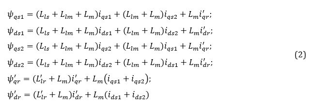
where flux linkages aligned with the direct and quadrature are calculated from equivalent circuit27 which assumes presence of two similar three phase windings sets in the stator with their leakage inductance Ll1 and mutual leakage inductance between two stator winding sets Llm. Stator of equivalent circuit has two direct current supply voltages vqs1 and vqs2 in reference frame with d and q axis. Rotor is supplied by voltages vds1 and vds2 which are assumed equal to zero for cage type rotor. The other notations as R1 denotes stator resistor, R'2 is rotor resistance referred to stator, Lm is magnetizing inductance and Llm is mutual leakage inductance between two stator windings, Lls is stator leakage inductance, L'lr is rotor leakage inductance,iqs1 and iqs2 are stator q axis current components,ids1 and ids2 are stator d axis current components, iqr and idr are rotor current components in q and d axis accordingly are calculated:


where ωr is motor rotational velocity, Jr is rotor inertia, Te is electromagnetic torque and TL is load torque.
Analysis of multiphase motor dynamics applies all general assumption for electrical machines. Three phase machine transformation from the stationary three phase reference frame A-B-S to two-phase stationary reference frame ds-qs and synchronously rotating reference frame d-q is described in,29 where the stator voltage vas axis is aligned with vq axis. The transformations are made in this way. If stationary ds-qs axes of three phase machine are oriented at angle θ, the voltages vsds and vsqs can be represented in matrix form as:

where vs0s is zero component. In balanced machine vsds=0. Usually, θ is assumed equal to zero. Inverse transform of (5) can be made in this way:

The synchronously rotating d-q axes rotate with synchronous speed ωe with respect to ds-qs axes and form the angle θe=ωet. The voltages on ds-qs axes are transformed into d-q axes by this way:

According to reference frame transform theory, set of three phase voltages vD, vE, and vF shifted by 1200 apart, starting with phase voltage vD lagging the voltage vA by 600, could be transformed to stationary reference frame in this way:


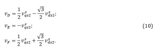
According to Equation 9, sinusoidal variables in D-E-F reference frame appear as sinusoidal quantities in rectangular reference frame vsqs2 and vsds2. Voltages vsqs2 and vsds2 scan be transformed to synchro-nously rotating reference frame like this:

Thus, we considered two transforms for two three phase voltage sets vA-vB-vC and vD-vE-vF. The voltages are shifted by 120 electrical degrees in each set. These sets are transformed to stationary rectangular reference frame with equations (5) and (8). The variables from rectangular stationary reference frame are transformed to synchronously rotating reference frame using equations (7) and (11). Simulink model of six phase motor elaborated on the (1), (2), (3) and (4) and is given.28 The block diagram in Figure 1 shows elaborated Simulink model of six-phase drive with indirect field-oriented control and PID and PID fuzzy controllers.
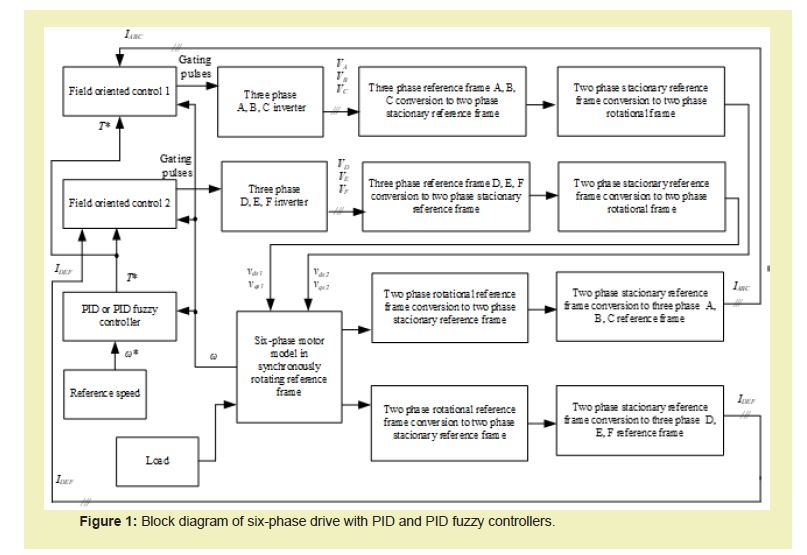
Reference speed is compared with motor speed Figure 1 in PID or PID fuzzy controller. The controller elaborates reference torque signal for two field-oriented blocks. Block “Field oriented control 1” produces gating pulses for three phase converter tuned to generate three phase voltage set VA, VB and VC. The next block transforms three phase voltages to two phase voltages in stationary reference frame and the last conversion transforms two phase stationary to rotational reference frame, and forms two voltages vds1 and vqs1. Block “Field oriented control 2” elaborates gating pulses to three phase inverter, tuned to produce voltage set VD, VE and VF. Voltage VD lags voltage VA by 60 electrical degrees. This voltage set is transformed to two phase stationary reference frame and afterwords to two phase rotating reference frame and gives two voltage vds2 and vqs2 entering as input signals to six-phase motor model. Motor currents ids1, iqs1 and ids2, iqs2 in two phase rotational reference frame are output of motor model. Each pair of currents are converted to two phase stationary reference frame ids1, iqs1 with Equation 6, where voltages should be replaced by currents and for ids2, iqs2: Equation 9; afterwords they are transformed to two sets of three phase currents IA, IB, IC and ID, IE,IF, used as feedback for two field oriented control blocks, elaborating gating pulses according to produced torque reference signal and calculated motor currents.
Gating pulses change voltages and finally motor speed in the control system follows the speed reference. Fuzzy controller is one of intelligent controllers, suitable for systems even having no mathematical model. Fuzzy control is nonlinear control. The six-phase motor d-q model in the rotating reference frame based on the equivalent motor circuit with two stator windings and a single rotor winding is a non-linear complex model, which can have variable parameters and load disturbance. The fuzzy controller can control similar systems. Operation of fuzzy logic controller is based on sets. Fuzzy logic controller consists of fuzzification block, the knowledge base, and the inference engine. Fuzzification block of fuzzy controller transforms crisp inputs into fuzzy sets.19 Seven linguistic variables related to the membership functions, are used to describe the fuzzy sets: PB (Positive Big), PM (Positive Medium), PS (Positive Small), ZE (Zero), NS (Negative Small), NM (Negative Medium), NB (Negative Big). The designed system controller is based on the error, and the integral error and error derivative as inputs. Each set represents several linguistic variables defining the possible state of the output. The knowledge base consists of the membership functions and the fuzzy rules, which are obtained by knowledge of the system operation according to the environment for example, provided speed reference or application of load. Knowledge base defines the rules represented by IF-THEN rule base, relating the input and output variables. Designed controller comprises 49 rules.
The inference engine, which is based upon the input fuzzy sets, uses the IF-THEN rules in the knowledge base to make the decisions. Knowledge base relates 49 IF-THEN rules and membership functions to produce the fuzzy output. The defuzzification process converts the fuzzy output variables to crisp output. Designed fuzzy controller was based on per unit membership functions.
Model of indirect rotor flux orientation
According to30 in indirect field-oriented control, rotor flux vector is aligned with the axis d of the revolving d-q reference frame. Two reference frames stationary ds-qs and revolving at synchronous speed d-q are shifted by the angle θe between two reference frames. Angle between two reference frames θe varies with rotor rotation. Rotor flux Ψ ̅ris aligned with the axis d and its projection to the d axis Ψrd=|Ψ ̅r | and Ψrq= 0. Then torque, delivered by an induction motor is calculated as:

where p is number of poles and isq is torque producing current, Lm is magnetizing inductance and L'r is rotor inductance, referred to stator. Current isq is calculated in rotating reference frame from chosen speed reference ω*r and current i*sq from given flux reference Ψ*r, rotating at synchronous speed ω0.

The angular position of Ψ_ris reference frame orientation angle and is calculated as:

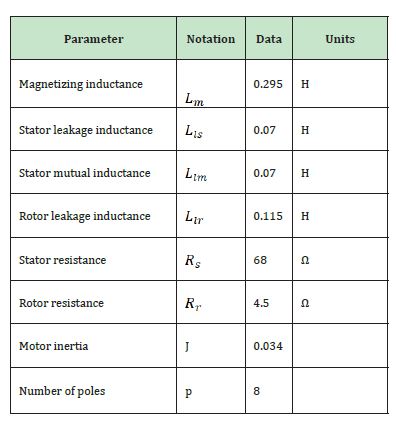
where ωm is measured mechanical speed of the motor, τr=(L'r)/Rr is rotor time constant, isd reference current, calculated from reference flux Ψr, ω*sl=i*sq/τri*sd is slip speed. Vector control Simulink model of six-phase motor enters the Simulink model of total six-phase drive shown in Figure 1. The small power motor parameters were measured experimentally performing locked rotor and no-load tests. They are given in Table 1.
PID and PID fuzzy controllers
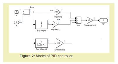
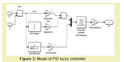
PID controller consist of parallel connection proportional, integral, and derivative controllers as shown in Figure 2. KP, PI and KD are tuneable gains. K3 defines the final value of output signal „Torque reference “, required for control system.The system gains were chosen to get the best step response specifications: KP = 1; KI = 0.01; KD = 0.001 and K3 = 25. Model of PID fuzzy controller is shown in Figure 3. It consists of the same PID controller, supplied with fuzzy controller. Fuzzy controller has two inputs: sum of proportional and integral error composes one input; error derivative forms the other input. Fuzzy logic controller is designed with unit membership functions for inputs and output [15]. It comprises 49 rules to calculate output according two input signals. Both PID and PID fuzzy controllers had the same tuned gains KP = 1; KI = 0.01; KD = 0.001; K3 = 25.
Simulation results system with PID controller
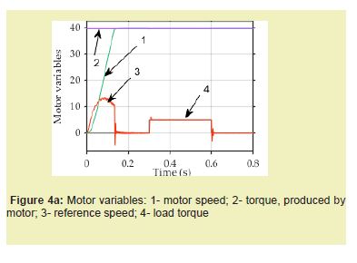
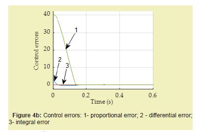
Step response of system with PID controller: Step response of field-oriented control system with PID controller of six-phase drive is shown in Figure 4a. Figure 4a indicates, that motor speed approaches to set-up speed 40 rad/s without overshoot. Setling time is 0.13 s. Load, applied at 0.3 s, shows negligible short time increase of motor produced load. The speed reduces with load by 0.4% and that is cancelled over 0.01 s. Control errors: proportional error, differential error and integral error are shown in Figure 4b. Proportional error is the greatest error. Torque reference signal is formed from sum of proportional error, differential error, and integral error. The sum is amplified by K3 = 25.
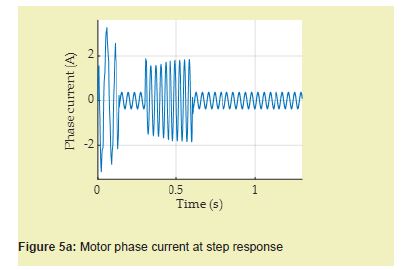
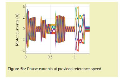
Figure 5a shows motor phase current at step response. At starting the greatest current value reaches 2.8 A. When motor speed reaches steady state, phase current reduces up to 0. 3 A and with the load applied at t = 0.3 s, it again raises to 1.8 A. With cancelling of load, the current comes back to its steady-state no-load value. Figure 5b gives change of all six-phase currents at provided step response Figure 6a. During acceleration motor currents raise up to 3.5 A. When motor speed reaches steady state, the current is the same as in Figure 5a. Applied load of 5 Nm at t = 0.3 s increases current to the same value as in Figure 5a. The load is taken off at t = 0.6 s when the motor goes to deceleration and currently motor speed is reversed. Currently the significant currents raise up to starting current is noticed. Current reduces again at motor speed reaches steady state. Afterwards motor decelerating increases current up to 4 A. After this motor speed is set to zero and sum of all phase currents becomes equal to zero.
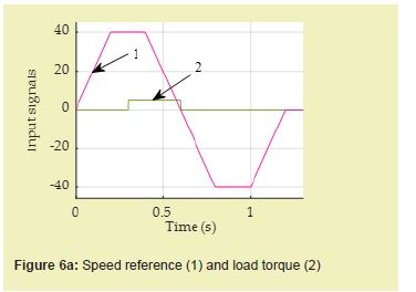
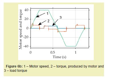
Simulation results of system with PID controller and provided reference speed: Figure 6 shows speed reference, load torque as input signals and motor response. Most of the motors should follow reference speed, with acceleration, steady state, deceleration following the reverse acceleration, steady state, and deceleration towards zero speed as shown in Figure 6a. When motor speed reaches steady state, the load of 5 Nm is applied at time instant t = 0.3 s. Figure 6b shows the actual motor speed (1), motor produced torque (2) and load torque. Application of load instantly increases motor torque up to 5 Nm. With deceleration motor torque becomes negative and afterwards it changes to provide reference speed.
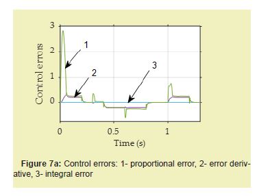
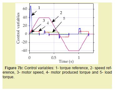
Figure 7a shows control errors: proportional error, error derivative and integral error at provided reference speed. The greatest is proportional error with its value of 2.8 rad/s at initial stage of starting. Figure 7b indicates torque reference, speed reference, actual motor speed, motor produced torque and load torque. At starting PID controller elaborates great torque reference, equal to 70 Nm, which in real equipment hardly could be achieved.
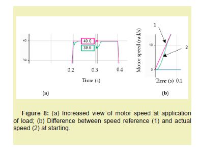
Figure 8a presents increased view of motor speed at application of load and difference between speed response and actual speed at starting Figure 8b. Motor speed reduces by 1% and this is eliminated after 0.03 s, remaining constant steady state error 0.075%. Initial speed delay lasts about 0.06 seconds. At this time a small delay of speed can be seen, nevertheless after 0.06 s motor speed exactly follows reference speed.
Simulation results with PID fuzzy controller
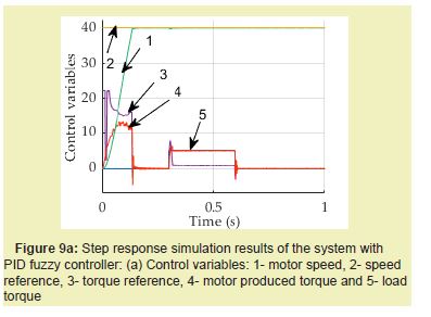
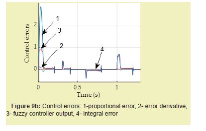
Step response of system with PID fuzzy controller: Step response of vector controlled six-phase drive with PID fuzzy controller is shown in Figure 9a. Motor speed without overshoot reaches steady state value. With application of 5 Nm load, motor speed reduces by 1%. Settling time is close to 0.13 s. Figure 9b indicates proportional error being the greatest error, its maximum value reaches about 2.8 rad/s. Figure 9b evidently shows nonlinear behaviour of fuzzy controller. Fuzzy controller output is 0,86. Amplified fuzzy controller output Figure 9a at starting does not exceed 22 Nm.
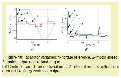
Simulation results of system with PID fuzzy controller and provided reference speed: Speed reference and load torque shown in Figure 10a were used as main inputs for the system with PID fuzzy controller. Reference torque, produced by PID fuzzy controller output and amplified is 22 Nm, which is much smaller than with PID controller, shown in Figure 9b. Control errors are shown in Figure 10b. Maximum value of proportional error reaches 2.8 rad/s, differential error changes its sign ad does not exceed 0.1 rad/s2 and integral error is small.
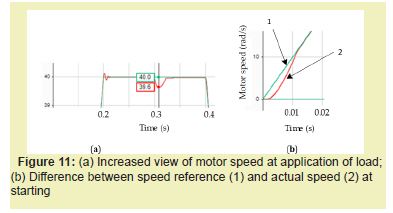
PID together with fuzzy controller improves transient specifications: speed decreases from load in the same way, but it is removed more quickly; nonlinear fuzzy controller output controls motor currents to deliver required torque, which maximum value 13 Nm is the same as without fuzzy controller. All motor variables are shown in Figure 10a. Figure 11a presents increased view of motor speed at application of load. It reduces by 1% and after short time - 0.012 seconds is removed. Difference between speed reference and actual speed at starting lasts 0.012 s. Figure 11b.
The simulink model for six-phase drive together with two PID and PID controllers is designed and simulated. Both systems indicate good step response and transients’ specifications. Speed decrease with load is the same for both systems, it does not exceed 1% and is removed quickly: with PID controller after 0.03 s, remaining constant steady state error 0.075%. PID fuzzy controller removes decrease in 0.012 s and has no steady state error. PID fuzzy controller follows reference speed more exactly after 0.012 s there is no error between reference and actual speed. PID controller operates more slowly, and error disappears after 0.06 s. Reference torque, produced by PID fuzzy controller output and amplified is 22 Nm, and that with PID controller reaches about 70 Nm. Nevertheless, motor cannot produce torque, greater than 13 Nm for both cases. This value corresponds to calculated breakdown torque.
Elaborated Simulink model of six-phase motor drive, controlled with PID and PID fuzzy controllers or separate its parts can be applied to control of real time systems. Both controllers providing good transient response specifications, develop robust systems. PID fuzzy controller indicates more exact following of speed reference at beginning of the process.
Conceptualization, Roma Rinkeviciene and Brone Mitkiene; methodology, Roma Rinkeviciene; software, Roma Rinkeviciene; validation, Roma Rinkeviciene, Brone Mitkiene; formal analysis, Brone Mitkiene; investigation, Roma Rinkeviciene; resources, Brone Mitkiene; writing-original draft preparation, Roma Rinkeviciene; writing-review and editing, Roma Rinkeviciene.
None.
This Research Article received no external funding.
Regarding the publication of this article, the authors declare that they have no conflict of interest.
- 1. E Levi. Multiphase electric machines for variable-speed applications. IEEE Transactions on Industrial Electronics. 2008;55(5): 1893-1909.
- 2. Andrey V Brazhnikov, Ilya R Belozerov. Prospects for the use of Multiphase Inverter-fed Asynchronous Drives in the Field of Traction Systems of Railway Vehicles. International Journal of Railway. 2012;5(1):38-47.
- 3. V Bugade. Multiphase Induction Motor Drive for Energy and Electrical Transportation Applications. Int J Res Appl Sci Eng Technol. 2018;6(4):166-174.
- 4. Akpama EJ. Six Phase Induction Motor Modelling for Submarine Application. IOSR Journal of Electrical and Electronics Engineering. 2018;13(1):61-66.
- 5. Abdelwanis MI, Selim F. A sensorless six-phase induction motor driving a centrifugal pump system. International Middle-East Power Systems Conference. 2017;242-247.
- 6. Rao YLN, Ravindranath G. A novel electric vehicle control - electronic differential - strategy using five phase induction motor. 2018;153–159.
- 7. Salem A, Narimani M. A Review on Multiphase Drives for Automotive Traction Applications. IEEE Transactions on Transportation Electrification. 2019;5:1329-1348.
- 8. Listwan J, Oleszczyszyn P. Analysis of the Drive of the Electric Vehicle with Six-Phase Induction Motor. Power Electronics and Drives. 2023;8.
- 9. Cao W, Mecrow BC, Atkinson GJ, et al. Overview of electric motor technologies used for more electric aircraft (MEA). IEEE Transactions on Industrial Electronics. 2012;59:3523-3531.
- 10. Xie J, Shi W, Shi Y. Research on Fault Diagnosis of Six-Phase Propulsion Motor Drive Inverter for Marine Electric Propulsion System Based on Res-BiLSTM. Machines. 2022;10:736.
- 11. Mesai Ahmed H, Jlassi I, Marques Cardoso AJ, et al. Multiple Open-Circuit Faults Diagnosis in Six-Phase Induction Motor Drives Using Stator Current Analysis. IEEE Trans Power Electron. 2022;37:7275-7285.
- 12. Antunes HRP, Fonseca DSB, Cardoso AJM. Modeling of Symmetrical Six-Phase Induction Machines Under Stator Faults. IEEE Trans Ind Appl. 2023;59:3232-3242.
- 13. Singh GK, Iqbal A. Modeling and analysis of six-phase synchronous motor under fault condition. Chinese Journal of Electrical Engineering. 2017;3:62-75.
- 14. Levi E, Bojoi R, Profumo F, et al. Multiphase induction motor drives–a technology status review. IET Electr Power Appl. 2007; 1:489-516.
- 15. Mandal S. Performance Analysis of Six-Phase Induction Motor. International Journal of Engineering Research & Technology. 2015;4:589-593.
- 16. Nabi HP, Dadashi P, Shoulaie A. A novel structure for vector control of a symmetrical six-phase induction machine with three current sensors. 10th International Conference on Environment and Electrical Engineering. 2011;pp.1-5.
- 17. Aher KS, Thosar AG. Modeling and Simulation of Five Phase Induction Motor using MATLAB/Simulink. 2016; 6:1–8.
- 18. Gregor R, Barrero F, Toral S, et al. Realization of an asynchronous six-phase induction motor drive test-rig. Renewable Energy and Power Quality Journal. 2008;1:101–105.
- 19. Zhao Y, Collins EG. Fuzzy PI control design for an industrial weigh belt feeder. IEEE Transactions on Fuzzy Systems. 2003;11: 311–319.
- 20. Renukadevi G. Rajambal K. Generalized model of multi-phase induction motor drive using matlab/Simulink. In 2011 IEEE PES International Conference on Innovative Smart Grid Technologies-India, ISGT India. 2011;114–119.
- 21. Venter P, Jimoh AA, Munda JL. Realization of a ‘3 & 6 phase’ induction machine. 20th International Conference on Electrical Machines. 2012;pp.447–453.
- 22. Akpama EJ, Anih LU. Modelling and Simulation of Multiphase Induction Machine. International Journal of Engineering Innovation & Research. 2015;4:2277–5668.
- 23. Vukosavic SN, Jones M, Levi E, et al. Rotor flux-oriented control of a symmetrical six-phase induction machine. Electric Power Systems Research. 2005;75:142–152.
- 24. Rinkevičicne R, Mitkienė B, Udris D. Modelling and Comparison PID Fuzzy Controllers for Six-phase Drive. In 2023 IEEE Open Conference of Electrical, Electronic and Information Sciences (eStreamAp). 2023;pp.1–5.
- 25. Rinkeviciene R, Mitkiene B, Udris D. Modelling of Six-Phase Electric Drive with PI and PD Fuzzy Controllers. 2021 IEEE Open Conference of Electrical, Electronic and Information Sciences, eStream. 2021;pp.1-6.
- 26. Rinkeviciene R, Mitkiene B, Udris D. Design and Comparison of Fuzzy Controllers for Six-phase Drive. 2020 IEEE Open Conference of Electrical, Electronic and Information Sciences, eStream. 2020;pp.1-5.
- 27. Singh GK. Multi-phase induction machine drive research - A survey. Electric Power Systems Research. 2002;61:139-147.
- 28. Kundrotas B, Lisauskas S, Rinkeviciene R. Model of multiphase induction motor. Elektronika ir Elektrotechnika. 2011;111:111-114.
- 29. Passino KM, Yurkovich S. Fuzzy control. In The Control Systems Handbook: Control System Advanced Methods 2nd (edn) 2010.
- 30. Bose BK. Modern power engineering and electric drives. 2002.

